
Related Manuals for emaux IHP13

Summary of Contents for emaux IHP13
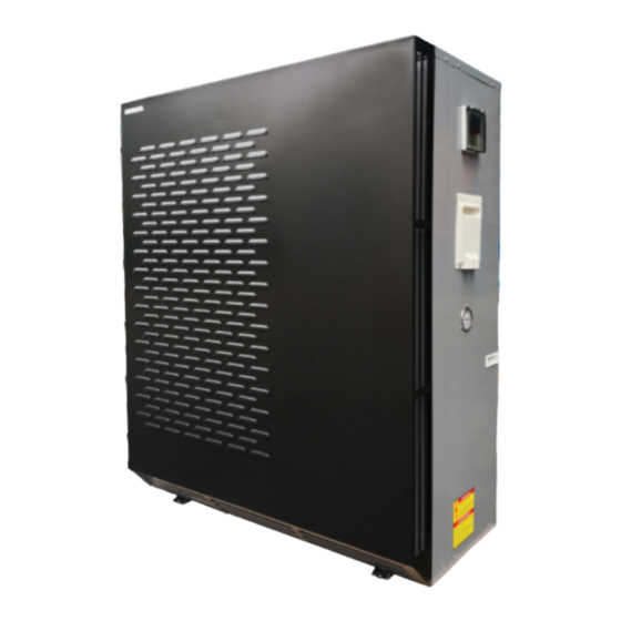
- Page 1 Invertor Heat Pump Operations manual EMAUX WATER TECHNOLOGY CO., LTD USER MANUAL STRIVE FOR CLEAR WATER www.emauxgroup.com Model: IHP13/IHP18/IHP21/IHP26/IHP36/IHP36S EMHE22022507...
-
Page 2: Table Of Contents
WARNINGS: TABLE OF CONTENT The installation, disassembly and maintenance of this appliance must be done by a qualified installer. It is forbidden to make any changes to the structure of the appliance. Failure to comply ..PRODUCT OVERVIEW with these provisions can cause damage to people, animals or things. 1.1 Specifications 1.2 Dimension .. - Page 3 2.Since the cautionary items shown here are important for safety, be sure to observe All the drawings shown in this manual relating to electrical, them. hydraulic or gas installation systems must be understood to be 3.After reading this manual, keep it together with the installation manual in a handy purely illustrative.
- Page 4 Do not connect the power cord to an intermediate point, use an extension Do not insert your finger, a stick, or other objects into the air inlet or outlet. cord, or connect multiple devices to heat pump. - This may cause injury, since the fan inside rotates at high speeds during - This may cause overheating, fire or electric shock.
- Page 5 Caution Do not operate switches with wet hands. - This may cause electric shock. Do not touch the air inlet or the aluminium fins of the heat pump unit. - This may cause injury. Do not clean the heat pump with water or place an object that contains water, such as a flower vase, on it.
-
Page 6: Product Overview
- If an earth leakage breaker is not installed, it may cause electric shock (mm) cover) (mm) (mm) (mm) 31000001 IHP13 1170*415*800 1170*515*800 970*370*650 970*470*650 Ensure that the drain water is properly drained. - If the drain passage is improper, water may drip down from the unit, wetting and... -
Page 7: Location
2. LOCATION Lift the front panel up 2.1 Location and Space Requirement 1. The air source heat pump must be installed outdoors. It cannot be installed indoors. 2. Never install the unit in a closed room with a limited air volume in which the air expelled from the unit will be reused, or close to garden plants that could block the air inlet. -
Page 8: Water Connection
2.4 Water Connection Valve 1: Slightly closed The following retail components (not included) are recommended for the hydraulic (Water pressure increase with just 100 to 200gr) connections: Valve 2: 1.Cut-of valves upstream and downstream from the heat pump to facilitate maintenance Completely open and/or heat pump bypass from the pool water circulation system. -
Page 9: Electrical Connection
2.7 Electrical Connection 2.8 Before Starting Make sure the pool is filled with water to the correct level, the skimmer and suction fittings are below the water level. Caution: To heat the pool water, the filter pump must be running to cause the water to circulate 1. -
Page 10: Display And Operation
after this time delay expires. Even a brief power interruption will trigger this time delay and prevent the unit from restarting immediately. Additional power interruptions during this delay period do not affect the 1 to 2-minute duration of the delay. Water Flow Switch The heat pump is equipped with a flow switch to protect it from running without adequate water flow rate. -
Page 11: Structure Of Interface Display
3. 3 Structure of Interface Display Press key to enter next stage interlace, press key to next mask in same stage. 3. 4 The Main Masks of Controller This is the main screen when the unit is power on. Parameters setting by pressing keys P19 DISPLAY AND OPERATION DISPLAY AND OPERATION... -
Page 12: Unit On/Off
3.5 Unit On/Off 3.8 Turbo Mode Changing TYou can turn the unit On/Off in Unit On Off mask page. You can set the temperature in this main mask by pressing key Press key then TYou can turn the unit On/ Press key to turn the unit Off in Unit On Off mask page. - Page 13 Keep pressing key P23 DISPLAY AND OPERATION DISPLAY AND OPERATION...
-
Page 14: Timezone /Clock Setting
3.11 Timezone /Clock setting 3.12 User Figures Setting You can set the Date, Clock and Timezone of unit running. You can set the user figures after go into this setting page. P25 DISPLAY AND OPERATION DISPLAY AND OPERATION... -
Page 15: Professional Program Setting (For Professional Technician Only)
3.14 Alarm Checking 3.13 Professional Program Setting (for professional technician only) You can set the professional figures with Login Password. Call your technical support to find the password. Press key to start program setting. You can set the advanced parameters of the unit (it need password to login). 4. - Page 16 Disposal and Decommissioning Spring Startup Collecting recyclable material, both those used for packaging (cardboard, nylon, etc.) If the heat pump has been winterized, perform the following steps when starting the and those replaced during routine and major maintenance is recommended. Suitable system in the spring: collection of waste material for recycling, processing and environmentally compatible 1.
-
Page 17: Troubleshooting
5. TROUBLESHOOTING Fault Cause Solution The appliance doesn’t 1. No power supply. Check the power supply. start Verify that the circuit is not open and that it is properly 2. The fuse on the gas side control board has grounded. Replace the fuse and reset the switch. Check tripped or the switch is open. -
Page 18: Alarm Code List
Alarm 6. ALARM CODE LIST Description Possible Cause Solution Code The DC voltage of the intermediate Alarm Possible circuit is below the limits In the event of temporary cut-off of the power Description Solution Code Cause AL54 Power+ alarm: Undervoltage envisioned due to: supply, reset the alarm and re-start the drive. -
Page 19: Diagrams
Alarm Code Description Possible Cause Solution 7. DIAGRAMS Safety AL79 Power+ alarm: intervention Check the wiring connection between AL114 Power+ alarm: Drive connection alarm 7.1 Wiring Diagram Power Drive and controller AL115 EEV alarm: Superheat of EEV is too low Contact your technical support AL116 EEV alarm:... - Page 20 DIAGRAMS DIAGRAMS P38...
-
Page 21: Terms Of The Warranty
During the warranty period, Emaux authorized reseller will repair or replace defective parts with new parts or, at the option of Emaux, serviceable used parts that are equivalent or superior to new parts in performance. This Limited Warranty extends only to products purchased from Emaux authorized reseller.
Need help?
Do you have a question about the IHP13 and is the answer not in the manual?
Questions and answers