
Subscribe to Our Youtube Channel
Related Manuals for Varian L6280

Summary of Contents for Varian L6280
- Page 1 vacuum technologies Block Valves INSTRUCTION MANUAL All Sizes Manual No. 699912040 Revision L September 2004...
- Page 2 Block Valves: Instruction Manual for All Sizes ConFlat Flange is a registered trademark of Varian, Inc. Klamp-Flange and KF Clamp are registered trademarks of Varian, Inc. Krytox is a registered trademark of DuPont Company Loctite is a registered trademark of Loctite Corporation.
- Page 3 Block Valves: Instruction Manual for All Sizes Warranty Products manufactured by Seller are warranted against defects in materials and workmanship for twelve (12) months from date of shipment thereof to Customer, and Seller’s liability under valid warranty claims is limited, at the option of Seller, to repair, to replace, or refund of an equitable portion of the purchase price of the Product.
- Page 4 Block Valves: Instruction Manual for All Sizes This page intentionally left blank.
-
Page 5: Table Of Contents
Block Valves: Instruction Manual for All Sizes Contents Preface ............................. xi Document Conventions ....................... xi Contacting Vacuum Technologies ....................xi Declaration of Conformity Introduction and Installation ......................1-1 Installation ..........................1-3 Electrical Connections to Solenoid ..................1-4 Operation ........................... 1-5 Manually-Operated Valves.................... - Page 6 Block Valves: Instruction Manual for All Sizes This page intentionally left blank.
- Page 7 Block Valves: Instruction Manual for All Sizes List of Figures Figure Caption Page KF Coupling......................... 1-3 Solenoid Assembly....................... 1-4 Solenoid Operation......................1-5 Small and Large Manual Block Valve – Exploded View............1-6 Small and Large Pneumatic Block Valve – Exploded View ..........1-11 Positioning the Quad Ring in the Air Cylinder..............
- Page 8 Block Valves: Instruction Manual for All Sizes This page intentionally left blank.
- Page 9 Block Valves: Instruction Manual for All Sizes List of Tables Table Title Page Valve Ordering Information NW16 – NW25................ 1-2 Valve Ordering Information NW50 – NW80................ 1-2 Small Block Valves: Manual Valve Parts List ................ 1-7 Large Block Valves: Manual Valve Parts List ................ 1-7 Small Valves: Pneumatic Valve Parts List ................
- Page 10 Block Valves: Instruction Manual for All Sizes This page intentionally left blank.
-
Page 11: Preface
Block Valves: Instruction Manual for All Sizes Preface Document Conventions This manual uses the following standard safety protocols: The warning messages are for attracting the attention of the WARNING operator to a particular procedure or practice which, if not followed correctly, could lead to serious injury. The caution messages are displayed before procedures, which CAUTION if not followed, could cause damage to the equipment. -
Page 12: Declaration Of Conformity
Declaration of Conformity Declaration of Conformity Konformitätserklärung Déclaration de Conformité Declaración de Conformidad Verklaring de Overeenstemming Dichiarazione di Conformità Varian, Inc. Vacuum Technologies Nous Nosotros 121 Hartwell Avenue Lexington, MA, 02421-3133 USA declare under our sole responsibility that the product, erklären, in alleniniger Verantwortung, daß... -
Page 13: Introduction And Installation
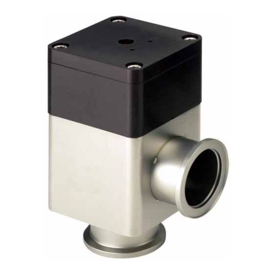
Block Valves: Instruction Manual for All Sizes Section 1. Introduction and Installation Vacuum Technologies small right-angle and in-line block valves are compact bellows-sealed valves for use in roughing and high vacuum applications. The valve body is ® made of aluminum or stainless steel, and incorporates Klamp-Flange , CFF or tube end fittings to provide reliable and convenient vacuum connections. - Page 14 Block Valves: Instruction Manual for All Sizes Table 1-1 Valve Ordering Information NW16 – NW25 Right-Angle, In-Line, All Models All Models Valve Material Part No. Part No. Manually-operated Aluminum L6280 L9180 Stainless Steel L9480 L9580 Pneumatically-operated Aluminum L6281 L9181 (with or without Stainless Steel L9481...
-
Page 15: Installation
Block Valves: Instruction Manual for All Sizes 1.1 Installation ® All valves are installed in a vacuum system by brazing welding, Conflat gaskets, or ® Klamp-Flange or KF couplings. KF coupling Consists of two symmetrical flange fittings (one of which is on the valve body), a centering ring, an O-ring and a flange clamp (Figure 1-1). -
Page 16: Electrical Connections To Solenoid
Block Valves: Instruction Manual for All Sizes 1.1.1 Electrical Connections to Solenoid To supply power to the solenoid: 1. Remove the connector from the solenoid by removing the holding screw and pulling the connector away from the solenoid. 2. Remove the terminal block from its housing by inserting a small, flat-head screwdriver in the slot provided at the terminal base and prying the housing off (Figure 1-2). -
Page 17: Operation
Block Valves: Instruction Manual for All Sizes 1.2 Operation This section discusses the operation of: ❑ “Manually-Operated Valves” ❑ “Pneumatically-Operated Valves” 1.2.2 Manually-Operated Valves The manual valve operates by means of a hand-actuated knob. To close the valve: ❑ Turn the knob in a clockwise direction. To properly compress the main O-ring seal and obtain a good vacuum seal, turn the knob clockwise until a slight resistance is felt, then firmly torque the knob approximately ¼... -
Page 18: Maintenance
Block Valves: Instruction Manual for All Sizes 1.3 Maintenance This section discusses the maintenance of: ❑ “Manual Valves” ❑ “Pneumatic Valves” on page 1-11 1.3.4 Manual Valves Manual valve maintenance consists of: ❑ “Disassembly and Cleaning” on page 1-8 ❑ “Reassembly”... - Page 19 Block Valves: Instruction Manual for All Sizes Table 1-3 Small Block Valves: Manual Valve Parts List Vacuum Technologies Part No. or Equivalent Item Description NW16 or NW25 NW40 Knob L5967301 (aluminum) L5698301 (aluminum) L8819001 (plastic) L8818001 (plastic) Set Screw #10-32 x 5/8 Ig #10-32 x 1/2 Ig Screw, Allen head cap #10-32 x 5/8 Ig...
- Page 20 Block Valves: Instruction Manual for All Sizes Table 1-4 Large Block Valves: Manual Valve Parts List (Continued) Vacuum Technologies Part No. or Equivalent Item Description NW50 ISO63 ISO80 Valve Body L6600001 L9970401 L9971401 Valve Body, L6600003 L9970003 L9971003 Nickel-plated 1.3.4.1 Disassembly and Cleaning Refer to Figure 1-4 on page 1-6 for this procedure.
- Page 21 Block Valves: Instruction Manual for All Sizes 5. Clean the internal metal components using an alcohol-dampened cloth or a light abrasive cloth such as Scotch-Brite™. When cleaning the parts of the bellows/valve stem assembly CAUTION (7, 8, 9, and 10; 5) , wipe only the surface area of the bellows and seal disk exposed to the vacuum system.
- Page 22 Block Valves: Instruction Manual for All Sizes 1.3.4.2 Reassembly Refer to Figure 1-4 on page 1-6 for this procedure. In this procedure, the components (shown in Figure 1-4, NOTE identified in Table 1-3 and Table 1-4) are enclosed in parentheses using the following convention: ❑...
-
Page 23: Pneumatic Valves
Block Valves: Instruction Manual for All Sizes 1.3.5 Pneumatic Valves Pneumatic valve maintenance consists of: ❑ “Disassembly and Cleaning” on page 1-14 ❑ “Reassembly” on page 1-16 ❑ “Position Indicator” on page 1-18 – discusses installation and servicing of the position indicator and microswitches Figure 1-5 shows an exploded view of the small pneumatic block valve and the large pneumatic block valve. - Page 24 Block Valves: Instruction Manual for All Sizes Table 1-5 Small Valves: Pneumatic Valve Parts List Vacuum Technologies Part No. or Equivalent Item Description NW16 or NW25 NW40 Air cylinder Cover L5484001 L5674001 Screw, Allen head cap #10-32x 2 Ig #10-32 x 2¼ Ig Visual Indicator Cap L5673-001 L5673001...
- Page 25 Block Valves: Instruction Manual for All Sizes Table 1-6 Large Block Valves: Pneumatic Valve Parts List Vacuum Technologies Part No. or Equivalent Item Description NW50 ISO63 ISO80 Air Cylinder Cover L6612001 L6612001 L9974001 Screw Allen Head Cap 1/4-20 x 21/4 lg 1/4-20 x 21/4 lg 1/4-20 x 21/4 lg Visual Indicator Cap L6611001 L6611001...
- Page 26 Block Valves: Instruction Manual for All Sizes 1.3.5.3 Disassembly and Cleaning Refer to Figure 1-5 on page 1-11 for this procedure. In this procedure, the components (shown in Figure 1-5, NOTE identified in Table 1-5 and Table 1-6) are enclosed in parentheses, using the following convention: ❑...
- Page 27 Block Valves: Instruction Manual for All Sizes 11. Ensure that the air cylinder (6) is still in the upside down position, using plastic tweezers or other nondestructive instrument, pull the quad ring (7) out of the center bore of the air cylinder (Figure 1-6).
- Page 28 Block Valves: Instruction Manual for All Sizes 15. Turn the bottom nut counterclockwise using the wrench. The nuts should not rotate with respect to the stem, instead the stem rotates with respect to the seal disc. Continue turning the stem until it separates from the seal disc. 16.
- Page 29 Block Valves: Instruction Manual for All Sizes To reassemble the valve: When completely rebuilding the valve, be sure to reassemble NOTE with new O-rings, quad ring, and cylinder cup. 1. Wipe all O-rings (12 and 13; 14 and 15) clean and very lightly grease them with Dupont ®...
- Page 30 Block Valves: Instruction Manual for All Sizes 10. Place the quad ring (7) in its groove. 11. Push the piston cup (5) into the air cylinder (6) with the rubber-coated side down. 12. Place the air cylinder (6) onto the valve stem (8) with the rubber side of the piston cup (5) facing up.
- Page 31 Block Valves: Instruction Manual for All Sizes Figure 1-9 shows an exploded view of the position indicator and Table 1-7 lists the associated callouts. Note: Microswitch S1 mounts in the two upper holes. Note: Microswitch S2 mounts in the two upper holes. Figure 1-9 Position Indicator Assembly Exploded View 1-19...
- Page 32 Block Valves: Instruction Manual for All Sizes Table 1-7 Position Indicator Parts List Item Description Vacuum Technologies Part No. or Equivalent Holding Screw Included with item 1 Connector MPM 193-07N Gasket Included with item 1 Position Indicator Cover L5978001 Screw, Phillips head #6-32 x 1/4 Ig Connector Base MPM 193...
- Page 33 Block Valves: Instruction Manual for All Sizes 1.3.5.5.1 Disassembly/Reassembly Refer to Figure 1-9 on page 1-19 for this procedure: 1. Remove the holding screw (1) from the connector (2) and pull the connector off the connector base (6). 2. Remove the screw (5) from the position indicator cover (4) and lift the cover off the air cylinder cover (21).
- Page 34 Block Valves: Instruction Manual for All Sizes 1.3.5.5.3 Installing the Position Indicator Kit To install a position indicator kit: 1. Remove the cover (4) from the position indicator assembly by removing the electrical connector and the screw and lockwasher from the top cover. 2.
- Page 35 Block Valves: Instruction Manual for All Sizes 4. Wire terminal contacts as detailed in Figure 1-10. Microswitch S1 Microswitch S2 Figure 1-10 Wiring Diagram – Position Indicator 5. Push the terminal block back into the connector housing and snap it into place. 6.
- Page 36 Block Valves: Instruction Manual for All Sizes This page intentionally left blank.
-
Page 37: Appendix A. Technical Specifications
Block Valves: Instruction Manual for All Sizes Appendix A. Technical Specifications Table A-1 lists the block valve specifications. Table A-1 Block Valve Specifications NW 16 NW 25 NW 40 NW 50 ISO 63 ISO 80 Conductance 3 liters/sec 12 liters/sec 32 liters/sec 61 liters/sec 100 liters/sec 155 liters/sec ≤... - Page 38 Block Valves: Instruction Manual for All Sizes Table A-1 Block Valve Specifications (Continued) NW 16 NW 25 NW 40 NW 50 ISO 63 ISO 80 Position Indicator Actuator Microswitch Electrical rating 125/250 VAC, 5 A maximum Signal hookup NO or NC or both Microswitch life 250,000 cycles with 1 A load...
-
Page 39: Appendix B. Spare Parts Kits/Accessories And Replacement Parts
Block Valves: Instruction Manual for All Sizes Appendix B. Spare Parts Kits/Accessories and Replacement Parts Table B-1 lists the spare part kits by valve type. Table B-1 Spare Part Kits Valve Type Valve Part No. Manual NW 16 or NW 25* L6125301 NW 40* L6126301... - Page 40 Block Valves: Instruction Manual for All Sizes ® Table B-2 KF Clamp and Centering Ring Ordering Information KF Clamp with Centering Ring with Ratchet Closure Viton O-ring KF Fitting Part No. Part No. NW16 KQ16AR KC16SV NW25 KQ25AR KC25SV NW40 KQ40AR KC40SV NW50...
-
Page 41: Request For Return Health And Safety Certification
4. If a product is received at Varian, Inc. in a contaminated condition, the customer is held responsible for all costs incurred to ensure the safe handling of the product, and is liable for any harm or injury to Varian, Inc. employees occurring as a result of exposure to toxic or hazardous materials present in the product. - Page 42 9001 Request for Return R E G I S T E R E D Health and Safety Certification FAILURE REPORT (Please describe in detail the nature of the malfunction to assist us in performing failure analysis): URBO UMPS AND URBOCONTROLLERS Claimed Defect Position Parameters...
- Page 44 Fax: (31) 343 469961 Tel (39) 011 997 9 111 Fax: (39) 011 997 9350 Fax (39) 011 997 9 350 Brazil Varian Industria e Comercio Ltda. Japan Internet Users: Varian Vacuum Technologies Avenida Dr. Cardoso de Mello 1644 Customer Service and T echnical Support:...
Need help?
Do you have a question about the L6280 and is the answer not in the manual?
Questions and answers