Table of Contents
Advertisement
Quick Links
Advertisement
Chapters
Table of Contents

Subscribe to Our Youtube Channel
Related Manuals for KEB C6 AMM


Summary of Contents for KEB C6 AMM
- Page 1 C6 AMM INSTRUCTIONS FOR USE | C6 MONITOR Original manual Document 20196475 EN 00...
- Page 2 ...
-
Page 3: Table Of Contents
2.6.1 OSD (On Screen Display) ................................ 21 2.6.2 Status LED .................................... 22 Button cabling area (optional) ................................ 23 C6 AMM (RVL) .................................... 24 2.8.1 KEB Remotation System ................................ 24 2.8.2 Remotation area .................................. 25 2.8.3 Label position .................................... 26 Touchscreen .................................... 29 2.9.1 Standard tecnology .................................. 29 ... - Page 4 3.6.13 On‐Screen Display menu ................................. 48 3.6.14 Input Interface Setting ................................ 48 3.6.15 Brightness / Contrast ................................ 49 3.6.16 Color Adjustment ................................... 49 3.6.17 Image Setting .................................. 50 3.6.18 Tools ...................................... 51 3.6.19 Handle removal .................................. 52 Maintenance and service .................................. 53 Calibration of the touchscreen ................................. 54 4.1.1 Touchscreen Application Tips .............................. 55 ...
-
Page 5: Preliminary Information
SECTION Preliminary Information... -
Page 6: General Notes
SECTION 1 – Preliminary Information 1.1 General notes a) The information in this manual is subject to change and is in no way binding upon KEB Automation KG. b) KEB Automation KG is not responsible for technical errors or other omis‐ sions in the manual, and shall not accept any responsibility deriving from its use. 1.2 Trademarks All brands and product names mentioned in this manual are trademarks of their respective owners. 1.3 Instructions on disposal Il simbolo sul prodotto o sulla confezione indica che il prodotto non deve essere considerato come un normale rifiuto domestico, ma deve essere portato nel punto di raccolta appropriato per il riciclaggio di ap‐ parecchiature elettriche ed elettroniche. Provvedendo a smaltire questo prodotto in modo appropriato, si contribuisce a evitare potenziali conse‐ guenze negative per l’ambiente e la salute, che potrebbero derivare da IT uno smaltimento inadeguato del prodotto. Per informazioni più detta‐ gliate sul riciclaggio di questo prodotto, contattare l’ufficio comunale, il servizio locale di smaltimento rifiuti o il fornitore da cui è stato acquista‐ to il prodotto. The symbol on the product or in its packaging indicates that this product may not be treated as household waste. Instead it shall be ... -
Page 7: Description Of Safety Symbols
DE Das Symbol auf dem Produkt oder seiner Verpackung weist darauf hin, dass dieses Produkt nicht als normaler Haushaltsabfall zu behandeln ist, sondern an einem Sammelpunkt für das Recycling von elektrischen und elektronischen Geräten abgegeben werden muss. Durch ihren Bei‐ trag zum korrekten Entsorgen dieses Produkts schützen Sie die Umwelt und die Gesundheit Ihrer Mitmenschen. Umwelt und Gesundheit wer‐ den durch falsches Entsorgen gefährdet. Weitere Informationen über das Recycling dieses Produkts erhalten Sie von Ihrem Rathaus, Ihrer Müllabfuhr oder den Distributoren, in dem Sie das Produkt gekauft ha‐ ben. ES El simbolo en el producto o en su embalaje indica que este produc‐ to no se puede tratar como desperdicios normales del hogar. Este pro‐ ducto se debe entregar al punto de recolección de equipos eléctricos y electrónicos para reciclaje. Al asegurarse de que este producto se dese‐ che correctamente, usted ayudará a evitar posibles consequencias nega‐ tivas para el ambiente y la salud pública, lo qual podria ocurrir si este ... -
Page 8: Qualified Personnel
1.6 Basic knowledge required a) To understand operating instructions a general knowledge of automa‐ tion technology is needed. b) Knowledge of personal computers and the Microsoft o.s. is required to understand this user’s guide. 1.7 Proper use of the product a) KEB products may only be used for the applications described in the catalogue and in the technical documentation. b) If products and components from other manufacturers are used, these must be approved by KEB. c) Proper transport, assembly, installation, storage, commissioning, opera‐ tion and maintenance are required to ensure that the product operates safely. d) The indicated environmental conditions must be observed. e) The information in this user’s manual must be observed. 1.8 Purpose of the user’s guide a) This user’s manual contains information based on the requirements de‐... -
Page 9: Scope Of The Operating Instructions
1.9 Scope of the operating instructions The operating instructions apply to the C6 AMM family. The devices are the following: 15.6” W C6 AMM (DVI) resistive 18.5” W 21.5” W 15.6” W 18.5” W C6 AMM (DVI) capacitive 21.5” W Table 2 24.0” W C6 AMM family 15.6” W C6 AMM (RVL) resistive 18.5” W 21.5” W 15.6” W 18.5” W C6 AMM (RVL) capacitive 21.5” W 24.0” W 1.10 The manual is a part of the system a) This user’s guide belongs to C6 AMM and is also required for commis‐... -
Page 10: Safety Instructions
SECTION 1 – Preliminary Information 1.12 Safety instructions 1.12.1 Installation according to the instructions Commissioning the C6 AMM device is prohibited until it has been abso‐ lutely ensured that the system in which the C6 AMM device is to be in‐ stalled complies with all the applicable EU and international regulation. 1.12.2 Hazardous areas Do not use C6 AMM in hazardous areas. 1.12.3 Working on the control cabinet Danger Dangerous voltage Opening the cabinet may expose high voltage parts. Before opening the cabinet always disconnect the power. 1.13 Notes about usage C6 AMM is approved for indoor use only. ... -
Page 11: General Description
SECTION General Description ... -
Page 12: Product Description
SECTION 2 – General Description 2.1 Product description C6 AMM arm mounting monitors are made of a full cast Aluminium chassis, powder coated with anti‐scratch treatment, combining robustness with ergo‐ nomics and aesthetics. C6 AMM families are available with 15.6" and 21.5" in Wide 16:9 aspect ratio 16 million color TFT LED Backlight LCDs and Aluminium True Flat with 5 wires resis‐ tive touchscreen or Aluminium True Flat with glass projected capacitive Multi‐ touch‐screen front panels. C6 AMM (DVI) monitor family has VGA and DVI‐D input 24 VDC with galvanic isolation power input and two external access USB 2.0 ports. C6 AMM (RVL) family feature a built‐in up to 100 meters remotation for digital video and USB 2.0 signal, with a single cable. 2.2 Key features • Industrial arm mounting fanless PC. • Integrated configurable button area configurable with emergency but‐ ton, switches, buttons and, lights. • 5 wires resistive touchscreen C6 AMM resistive or Projective‐Capacity Multitouch‐screen C6 AMM capacitive. • Operating temperature 0°C to +50°C. ... -
Page 13: Lcd Led Backlight
2.2.2 LCD LED backlight LCD with LED backlight technology; the system is equipped only with the new generation LCD with LED technology. ... -
Page 14: Package
SECTION 2 – General Description 2.3 Package C6 AMM package consists of: C6 AMM n.1 Power supply plug (pre‐installed on the system) n.1 Power supply cover (DC systems only) Table 3 Package n.1 Eyelet terminal (pre‐installed on the system) n.1 Screwdriver n.4 Cups ... -
Page 15: Front
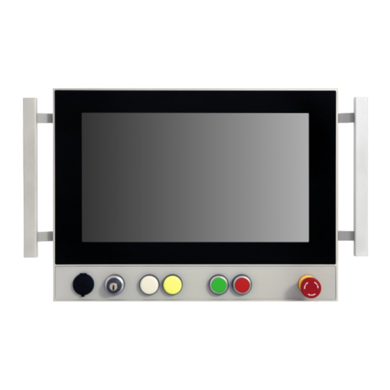
2.4 Front The system is available with two different frontal panels: Aluminium with True Flat technology (resistive). Aluminium with True Flat technology and Multitouch (capacitive). in the following sizes: 15.6” wide (16 : 9) Figure 2 C6 AMM 15.6” 21.5” wide (16 : 9) Figure 3 C6 AMM 21.5” ... -
Page 16: Resistive Front Panel
SECTION 2 – General Description 2.4.1 Resistive front panel C6 AMM resistive (aluminium front panel with true flat technology) is available in the following sizes: 15.6” wide (16 : 9) 18.5” wide (16 : 9) 21.5” wide (16 : 9) 1 2 3 Figure 4 3 Resistive panel. (in the figure is shown as an example a 15.0" display) 4 5 Aluminium front panel with top polyester film 1 Touchscreen display 2 Handles (optional) 3 Power on LED 4 Button area 5 The front panel with true flat technology has no “step” between the front panel and the touchscreen, therefore it can be easily cleaned. The polyester top‐film covers the resistive touchscreen up to the alu‐ minium border. ... - Page 17 4 3 2 1 Figure 6 Construction detail. Back seal 1 Metal housing 2 Touchscreen 3 Front laminate 4 ...
-
Page 18: Capacitive Front Panel
SECTION 2 – General Description 2.4.2 Capacitive front panel C6 AMM capacitive (aluminum and glass front panel with true flat technology with multitouch touchscreen) is available in the following sizes: 15.6” wide (16 : 9) 18.5” wide (16 : 9) 21.5” wide (16 : 9) 1 2 24.0” wide (16 : 9) Figure 7 Capacitive front panel. 3 3 (in the figure is shown as an example a 15.6" display) 4 5 Aluminum and tempered glass TrueFlat 1 Projective capacitive multitouch 2 Handles (optional) 3 Power on LED 4 Button area 5 The front panels with true flat technology contain a Projective capacitive multi‐ touch touchscreen that is handled by a USB controller within the system. ... -
Page 19: Button Area
3 2 1 Figure 9 Construction detail. Back seal 1 Metal housing 2 Touchscreen 3 2.4.3 Button area The system is equipped with a fully customizable button area. Figure 10 Button area detail. The button area can also be ordered without buttons. Figure 11 Button area detail. For further information please contact the KEB support. ... -
Page 20: Rear
SECTION 2 – General Description 2.5 Rear The back of the system contains dual USB 2.0 port protected by a screw cap and the connector area, protected by a removable cover. 1 3 Figure 12 2 Detail back of the system 5 5 4 Figure 13 Detail arm attack Fixed rear panel 1 Dual USB USB 2.0 port 2 Removable cover 3 Rittal CP40 attack 4 Handles (optional) 5 ... -
Page 21: Top/Bottom Arm Mounting
2.5.1 Top/Bottom arm mounting C6 AMM has to be installed on a swing arm system using an integrated flange. Depending of the customer’s order, the integrated flange can be ordered either on the top or on the bottom of the system (respectively for either top or bot‐ tom arm mounting). 1 1 Figure 14 2 Detail bottom arm mounting predisposition 3 2 Figure 15 Detail top arm mounting predisposition 1 1 Depending of the customer’s order the system can be with or without lateral handles (optional removable). Optional removable handles 1 Removable connectors cover 2 Integrated flange on bottom 3 ... -
Page 22: Rear Usb 2.0
SECTION 2 – General Description 2.5.2 Rear USB 2.0 The USB 2.0 port on the rear panel is protected by a screw cup that guarantees protection when completely closed. Figure 16 USB detail 1 USB cover 1 2.5.2.1 Opening / closing the cover Unscrew the cover. Figure 17 USB detail Warning The cover is attached to the system by means of a spring. Be careful not to tear the spring. Screw the cover. Verify that all edges of the cover perfectly adhere to the hole. ... -
Page 23: Connectors
2.5.3 Connectors To access the connectors it is necessary to remove the rear removable cover (refer to section 3.6.4 Accessing connector area). 1 Figure 18 Detail rear removable cover Rear removable cover 1 2 3 3 Figure 19 Detail connector area Connector area 2 Buttons cabling area 3 ... -
Page 24: Connector View
SECTION 2 – General Description 2.6 Connector view The connector area is composed by the following parts: Caution: In order to access to the rear panel con‐ nectors the system must be disconnected 8 from the power supply and put on a flat plane to remove the rear panel. 7 Figure 20 C6 AMM (DVI) Connectors 3 4 2 5 6 1 Figure 21 C6 AMM (RVL) Connectors 9 10 Figure 22 Connection terminals 11 11 Earth screw 1 Power supply socket ... -
Page 25: Osd (On Screen Display)
2.6.1 OSD (On Screen Display) Figure 23 C6 AMM OSD buttons Figure 24 C6 AMM OSD buttons detail + (←) - (→) Menù / Select... -
Page 26: Status Led
SECTION 2 – General Description 2.6.2 Status LED Figure 25 C6 AMM status LED Status LED Figure 26 C6 AMM status LED detail Status LED Status LED Green Correct video signal input Amber Unsupported video input Amber blinking No video input... -
Page 27: Button Cabling Area (Optional)
2.7 Button cabling area (optional) Figure 27 Button cabling area detail 1 1 Terminal for buttons cable connection 1 If the system is ordered without buttons, the terminals will not be present on the button cabling area. Figure 28 Button cabling area detail... -
Page 28: C6 Amm (Rvl)
The industrial monitor family C6 AMM (RVL) provides the remotation of DVI‐D and USB 2.0 signals that allows the connection to a IPC up to 100 meters away with Cat 5e SF/UTP cable. 2.8.1 KEB Remotation System The remotation system developed by KEB is based on the serialization of the DVI‐D and USB 2.0 signals that are transmitted, in a differential and strong way, by an Ethernet Cat 5e SF/UTP cable. The remotation kit is composed by a transmitting local module, 24V DC pow‐ ered and placed near the PC, and a receiver section integrated into KEB monitor family. This technology let you transmit high quality signals with Full HD resolution, up ... -
Page 29: Remotation Area
2.8.2 Remotation area Figure 30 Remotation area detail Remotation area Figure 31 Remotation area detail Remote input Link LED Run LED Power LED... -
Page 30: Label Position
SECTION 2 – General Description 2.8.3 Label position On the rear panel the following labels are present. 4 3 2 3 1 Figure 32 Labels position Marking label 1 Connectors label 2 Terminal label 3 Rear cover internal label (only if button area contains buttons) 4 2.8.3.1 Marking label 1 2 4 Figure 33 C6 AMM marking label detail 3 5 Model 1 ... - Page 31 2.8.3.2 Connectors label Figure 34 C6 AMM connectors (RVL) label detail Figure 35 C6 AMM connectors label detail 2.8.3.3 Terminal label Figure 36 Terminal label For further information please contact the KEB support. ...
- Page 32 SECTION 2 – General Description 2.8.3.4 Rear cover internal label Figure 37 Rear cover internal label ...
-
Page 33: Touchscreen
2.9 Touchscreen C6 AMM resistive and C6 AMM capacitive are provided with a 5‐wire touchscreen with a controller integrated on the motherboard. Touchscreen is available in different technologies C6 AMM resistive is available only with standard resistive touchscreen. C6 AMM capacitive is available only with projective capacitive multitouch‐ touchscreen. 2.9.1 Standard tecnology Touch surface is made of PET hard coated Film (Hardness: 3H). 2.9.2 Multi Touch tecnology Tempered glass and aluminium frame for the TrueFlat Multitouch (capacitive) front panel: Projected capacitive touchscreen (P‐CAP). Up to 4 finger operation. Gestures support. ... - Page 34 SECTION 2 – General Description...
-
Page 35: Installation And Connection
SECTION Installation and connection ... -
Page 36: Preparation For Installation
The mounting location should comply with the following characteristics: a) Avoid direct sunlight exposure. b) Make sure that C6 AMM is properly (ergonomically) accessible to the operator. c) Choose a suitable mounting height. 3.2 Checking the package contents Check the package content for visible signs of transport damage and for completeness. In the case of damaged parts, contact your KEB representative. Do not install parts that were damaged during the shipment. 3.3 Checking the operating conditions Read carefully the standards, approvals, EMC parameters and technical specifications for operation of the device. This information is available in the following sections: Certificates and approvals (refer to section 6.1.2 Certification and approvals). Electromagnetic compatibility (refer to section 6.1.2 Certifica‐ tion and approvals). Check the mechanical and climatic ambient conditions for operation of the device: Ambient conditions (refer to section 6.1.4 Technical data). ... -
Page 37: Mounting Position
3.4 Mounting position C6 AMM device is suitable for arm installation. 3.4.1 Damage due to overheating All C6 AMM systems are designed for vertical mounting position. A inclined installation reduces the thermal convection by C6 AMM and the maximum permissible ambient temperature for operation. Please contact KEB for details. C6 AMM may otherwise be damaged and its cer‐ tifications and warranty will be void. The ambient temperature must be between 0°C to +50°C measured 5 cm Note: For installation in control cabinets and, in from all openings of the system where there is air entrance. particular, in closed containers, make sure Provide space around the system for air recirculation and heat exchange. the recommended ambient temperature is Mounting angle: maintained. For further details please refer to section The system is intended to be mounted vertically. 5.1 Technical specifications For inclinations of more than 10° and up to 20° is necessary to de‐ crease the maximum operating temperature of 5°C. For other installation modes contact KEB Automation KG. 3.4.2 Degrees of protection ... -
Page 38: Dimensions
SECTION 3 – Installation and connection 3.5 Dimensions This section shows the dimensions of the systems. 3.5.1 C6 AMM Figure 38 C6 AMM dimensions Figure 39 C6 AMM dimensions LCD TFT A B C D E F Peso 15.6” 433 320 240 13.5 30 54 8.0 18.5” 503 358 276 14.5 36 91.5 10.0 21.5” ... -
Page 39: Mounting The Device
3.6 Mounting the device The system can be installed with three different adapter flanges: RITTAL™ CP40 Rolec Taraplus HASEKE ULT KUPPLUNG 3.6.1 Rittal CP40 adapting flange dimensions (for angolar attack) Figure 40 Rittal CP40 adapting flange detail 3.6.2 Rolec adapting flange dimensions Figure 41 Rolec adapting flange detail ... -
Page 40: Haseke Adapting Flange Dimensions
SECTION 3 – Installation and connection 3.6.3 Haseke adapting flange dimensions Figure 42 Haseke adapting flange detail ... -
Page 41: Accessing Connector Area
3.6.4 Accessing connector area Only screws can be removed by the user. Danger: Warning All the screws HAVE NOT to be removed for any reason. The operations described below must only be performed by qualified personnel. Tool required Action Exagonal screwdriver 2,5mm Screw / unscrew n.6 fixing screws On the back of the system remove the 6 fixing screws of the connector Warning: cover. Tighten the fixing screws with 0.7 Nm fixing torque. 1 1 1 ... - Page 42 SECTION 3 – Installation and connection Figure 45 Cover detail Now you have free access to the connectors area. Remove the cable retainer bracket. 1 1 Figure 46 Cable retainer bracket detail Screws to be loosed 1 ...
-
Page 43: Rittal Cp40 Support: Installation Example
3.6.5 Rittal CP40 support: installation example Slide the cables inside the arm (in the example below ground cable and, power supply cable). Figure 47 Installation example Carefully position the arm to the bracket and hang it with the 4 screws. Figure 48 Installation example Figure 49 Installation example... -
Page 44: Grounding And Bonding
SECTION 3 – Installation and connection 3.6.6 Grounding and bonding Whenever two pieces of equipment connected to each other are far apart, it is possible that their ground connections could be at a different potential Note: level. The data cable screens connecting the equipment’s chassis on one end It is suggested to connect the system to the ground wire by means of suitable wiring and the C6 AMM chassis on the other end can therefore be subject to a high (AWG14 or greater cross sections are current circulation capable of destroying the interface. To overcome this suggested). hazard such current must be steered away from the interface. To achieve this goal the following methods can be used: Figure 50 Power supply diagram 1. Use an equipotential bonding cable (16mm ) to connect the equipment’ ground to the C6 AMM ground. 2. -
Page 45: Power Supply Isolation
3.6.7 Power supply isolation The C6 AMM power supply is galvanically isolated which means its output is elec‐ trically separated from its input. This feature has many benefits: Increases the noise immunity of the system Avoids input short circuits in systems with the power supply grounded Breaks ground loops which may cause interferences in the video signals. 3.6.8 Wiring diagram The wiring diagram shows a simplified pictorial representation of the electrical circuit. It shows the components of the circuit as simplified shapes, and the pow‐ er and signal connections between the devices. Figure 52 Power supply connection detail ... -
Page 46: Power Connector Assembly
SECTION 3 – Installation and connection 3.6.9 Power connector assembly The system is equipped with a connector cup to be installed on the two poles power connector. To properly assemble the connector please follow these in‐ structions: Figure 53 Power connector assembly Insert the cable tie in the cup as shown in the picture. Figure 54 Power connector assembly Slide the cable tie as shown in the picture. Figure 55 Power connector assembly ... - Page 47 Place the two poles plug connector in the cup as shown in the picture. Figure 56 Power connector assembly Tighten the cable tie. Figure 57 Cup installation Cut the excess part. Figure 58 Cup installation ...
- Page 48 SECTION 3 – Installation and connection Insert the white label and close the cup as shown in the picture. Figure 59 Cup installation Example of a correctly installed cup. Figure 60 Power connector assembly ...
-
Page 49: Power On
3.6.10 Power on The system has to be connected to a 24 V (18‐32V ) power supply which satisfies the requirements of safe extra low voltage (SELV) in accordance with IEC/EN/DIN EN/UL60950‐1. Note: Remove the two poles plug connector from the system (the system is For further details refer to section 3.6.6 Grounding and bounding shipped with the power plug connected). Always check that the voltage drop along the supply wiring is not excessive and the input voltage remains above the minimum required (18V ) in the worst load condition. Connect the ground cables (PE) to the earthing points. Connect the positive and the negative poles (also refer to the label on the back of the system) to their respective terminals of the two pole plug con‐ nector. Use wires with a cross‐section of 1.5 mm2 (AWG16). Use the supplied screwdriver to fix the power connector to the system. Figure 61 Screwdriver detail Note: For further details refer to section 3.6.9 Power Connector assembly Figure 62 Power on sequence ... - Page 50 SECTION 3 – Installation and connection Lock the cables the cable retainer bracket. Figure 63 Power on sequence Warning: Check the adhesive gasket correctly adhere the cover when fixing it to the system after the connection. Re‐place the cover previously removed and fix it to the system. Note: For further details refer to section 6.1.10 Adhesive gasket technical data ...
-
Page 51: Osd (On Screen Display)
3.6.11 OSD (On Screen Display) Figure 64 OSD area Figure 65 Keys for OSD adjustment + (←) - (→) Menù / Select 3.6.12 OSD navigation OSD is carried out pressing push‐buttons Select +, – : Menù / Select: it selects the evidenced option, entering in an “under‐menu” or exiting from current menu (back option). With standing OSD, + enters in main menu. + (←): Increases the value of the selected control or select the next menu item. ‐ (→): Decreases the value of the selected control or select the previous menu item. ... -
Page 52: On-Screen Display Menu
SECTION 3 – Installation and connection 3.6.13 On-Screen Display menu Input interface Settings. Brightness / Contrast. Color Adjustment. Figure 66 On‐Screen Display menu Image setting. Tools. Exit. 3.6.14 Input Interface Setting Displays the input interface in use: Figure 67 ... -
Page 53: Brightness / Contrast
3.6.15 Brightness / Contrast Figure 69 OSD – Brightness / Contrast menu Brightness: adjust the brightness. Figure 70 OSD ‐ Brightness / Contrast sub‐menu Contrast: adjust the contrast. 3.6.16 Color Adjustment ... -
Page 54: Image Setting
SECTION 3 – Installation and connection 3.6.17 Image Setting Figure 73 OSD – Image Setting Menu Auto Config: Automatically adjust of Image Width, Phase, H‐Position, V‐ Position settings. Image Width: Regulate Image Width. Figure 74 OSD ‐ Image Setting sub‐menu Phase Adjustment: Correct flickering text or lines. H‐Position: Adjust screen horizontal position. V‐Position: Adjust screen vertical position. ... -
Page 55: Tools
3.6.18 Tools Figure 75 OSD – Tools menu OSD Settings. Restore the default settings. Restore the color settings. Figure 76 OSD ‐ Tools sub‐menu Restore the timming settings. Text readibility Dos Graphic Mode ... -
Page 56: Handle Removal
SECTION 3 – Installation and connection 3.6.19 Handle removal The system is provided of two handles. If for any reason the user wants to re‐ move then, follow the above sequence. Only screws can be removed by the user. Warning All the screws HAVE NOT to be removed for any reason. Tool required Action Exagonal screwdriver 2,5mm Unscrew n.4 fixing screws Replace the screws with the provided cups N.4 provided cups On the back of the system remove the 4 fixing screws of the handles. 1 1 Figure 77 Handles removal 1 1 Screws to be removed 1 Remove the handles and fill the holes with the provided cups. 1 1 Figure 78 ... -
Page 57: Maintenance And Service
SECTION Maintenance and service ... -
Page 58: Calibration Of The Touchscreen
SECTION 6 – Maintenance and service 4.1 Calibration of the touchscreen C6 AMM is designed to don’t require touchscreen calibration, but in some cas‐ es, like update of the operating system, you must recalibrate the touch screen. Note: On capacitive system the calibration is not Go to Control Panel or Click on system tray icon and open eGalax setup ap‐ required. plication. Figure 79 Calibration of the touchscreen Select ‘Tools’ tab Figure 80 Calibration of the touchscreen Select ‘4 point calibration’. A more accurate option is available: ‘Linearization’. Figure 81 Calibration of the touchscreen ... -
Page 59: Touchscreen Application Tips
User should follows the guide to touch and hold the blinking symbol in the calibration window until it shows “OK” to make sure that the utility can gather enough data for computation Figure 82 Calibration of the touchscreen 4.1.1 Touchscreen Application Tips Use large buttons and a simple interface Avoid complex user operations like double‐clicks, scroll bars, drop‐down menus, use of multiple windows or dragging. Remember that not all the operations that can be done using a mouse are equally comfortable using a touch screen. Give the user feedback as soon as the screen is touched. An immediate feedback on a successfully touch operation is very important to the user. The feedback can be either visual (changing button aspect / 3D effects) or audio (“beep” or “click” on touch). Turn the cursor off It will help the user to focus on the entire screen, without being distracted by the cursor pointer. Run your application full screen Remove title and menu bars, to use the entire display area. Avoid using a black background Bright backgrounds, possibly containing a pattern, are the better choice for re‐ ducing glare and for hiding fingerprints. ... -
Page 60: Maintaining & Cleaning
Switch off the C6 AMM device or lock the touch screen. b) Spray the cleaning solution onto a cleaning cloth. c) Do not spray directly onto the display. Warning: Do not use detergents, solvents, cleaners d) Clean the display from the screen edge inwards. or objects that could scratch the surface. 4.3 Technical support & repairs Warning: KEB offers wide‐ranging, complete after‐sales technical support. The staff who switch off the power before any cleaning operation. deal with this handle questions on the entire range of products skillfully, quick‐ ly, and efficiently. You can phone our staff in the service department, and they will give you com‐ plete, prompt advice on how to resolve your problems. telephone: +49 5263 401‐0 fax: +49 5263 401 116 e‐mai: combicontrol@keb.de 4.4 Recycling and disposal ... -
Page 61: Technical Specifications
SECTION Technical specifications ... -
Page 62: Certificates And Approvals
SECTION 8 ‐ Technical specifications 5.1 Technical specifications 5.1.1 Certificates and approvals Warranty & approvals Emission Conforms to: EN 61326-1 Electrical equipment for measurement, control and laboratory use. EMC requirements. General requirements EMC Directive 2014/30/EU Immunity Conforms to: EN 61326-1 Electrical equipment for measurement, control Table 6 ... -
Page 63: Technical Data
1 x VGA (DB15F) ▪ 1 x DVI-D Single Link ▪ 2 x USB 2.0 (Type A) ▪ 1 x faces USB 2.0 (HUB input, Type B) Environmental Operating temperature: 0° ÷ +50°C; Storage temperature: -5° ÷ +60°C; specifications Humidity: 80% (non-condensing) 12 months ▪ Warranty management by KEB headquarters Standard warranty ... -
Page 64: Table 9 Power Supply Technical Data
SECTION 8 ‐ Technical specifications 5.1.3.1 Power supply technical data Power supply Type Isolated DC- DC Isolation voltage 500 VAC Table 9 Input voltage 18÷32V DC Power supply technical data Input protection Reverse polarity circuitry Overvoltage 6.3A soldered fuse Power consumption 45W @ 24V (30W Typ.) Inrush current impulse Ipk : <... -
Page 65: Adhesive Gasket Tecnhical Data
5.1.4 Adhesive gasket tecnhical data The connector area is protected with a special gasket. Be careful when removing the cover, not to damage the gasket. 1 1 1 Figure 85 Adhesive gasket detail Adhesive gasket position 1 412/BT 130 Technical specifications Composition Silicone foam Cell structure Closed (15% open) Color White UNI 8457- UNI 9174 Class 1 a afnor nf 16 101 Class f 1 UL 94 Shore hardness 00 (ISO 2240) -
Page 66: Usb2 Type A Tecnhical Data
SECTION 8 ‐ Technical specifications 5.1.5 USB2 Type A tecnhical data Figure 86 USB3.0 detail Signal +5 Vcc USB Data - USB Data + 5.1.6 DVI-D tecnhical data Signal TMDS Data Channel 2- TMDS Data Channel 2+ Shield for TMDS Data 2/4 N.C. N.C. DDC Clock DDC Data Analog Vertical Sync TMDS Data Channel 1-... -
Page 67: Vga Tecnhical Data
5.1.7 VGA tecnhical data Signal Red video Green video Blu video ID GND DCC GND Red GND Green GND Blue GND DDC +5V ID GND Bi-Directional Data (SDA) H.Sync V.Sync Data Clock (SCL) 5.1.8 USB Type B tecnhical data Signal +5 Vcc Data - Data +... -
Page 68: Dimension Drawings
SECTION 8 ‐ Technical specifications 5.1.9 Dimension Drawings 5.1.9.1 15.6” bottom attack Figure 87 15.6” bottom attack dimensions Figure 88 15.6” bottom attack dimensions Figure 89 15.6” bottom attack dimensions ... - Page 69 Figure 90 15.6” bottom attack dimensions Figure 91 15.6” bottom attack dimensions Figure 92 15.6” bottom attack dimensions ...
- Page 70 SECTION 8 ‐ Technical specifications 5.1.9.2 15.6” top attack Figure 93 15.6” top attack dimensions Figure 94 15.6” top attack dimensions Figure 95 15.6” top attack dimensions...
- Page 71 Figure 96 15.6” top attack dimensions Figure 97 15.6” top attack dimensions Figure 98 15.6” top attack dimensions...
- Page 72 SECTION 8 ‐ Technical specifications 5.1.9.3 18.5” bottom attack Figure 99 18.5” bottom attack dimensions Figure 100 18.5” bottom attack dimensions Figure 101 18.5” bottom attack dimensions ...
- Page 73 Figure 102 18.5” bottom attack dimensions Figure 103 18.5” bottom attack dimensions Figure 104 18.5” bottom attack dimensions ...
- Page 74 SECTION 8 ‐ Technical specifications 5.1.9.4 18.5” top attack Figure 105 18.5” top attack dimensions Figure 106 18.5” top attack dimensions Figure 107 18.5” top attack dimensions...
- Page 75 Figure 108 18.5” top attack dimensions Figure 109 18.5” top attack dimensions Figure 110 18.5” top attack dimensions...
- Page 76 SECTION 8 ‐ Technical specifications 5.1.9.5 21.5” bottom attack Figure 111 21.5” bottom attack dimensions Figure 112 21.5” bottom attack dimensions Figure 113 21.5” bottom attack dimensions ...
- Page 77 Figure 114 21.5” bottom attack dimensions Figure 115 21.5” bottom attack dimensions Figure 116 21.5” bottom attack dimensions ...
- Page 78 SECTION 8 ‐ Technical specifications 5.1.9.6 21.5” top attack Figure 117 21.5” bottom attack dimensions Figure 118 21.5” bottom attack dimensions Figure 119 21.5” bottom attack dimensions ...
- Page 79 Figure 120 21.5” bottom attack dimensions Figure 121 21.5” bottom attack dimensions Figure 122 21.5” bottom attack dimensions ...
-
Page 80: Figure 124 21.5" Top Attack Dimensions
SECTION 8 ‐ Technical specifications 5.1.9.7 21.5” bottom attack with handles Figure 123 21.5” top attack dimensions Figure 124 21.5” top attack dimensions Figure 125 21.5” top attack dimensions ... -
Page 81: Figure 126 21.5" Top Attack Dimensions
Figure 126 21.5” top attack dimensions Figure 127 21.5” top attack dimensions Figure 128 21.5” top attack dimensions ... -
Page 82: Figure 129 21.5" Top Attack Dimensions
SECTION 8 ‐ Technical specifications 5.1.9.8 21.5” top attack with handles Figure 129 21.5” top attack dimensions Figure 130 21.5” top attack dimensions Figure 131 21.5” top attack dimensions ... -
Page 83: Figure 132 21.5" Top Attack Dimensions
Figure 132 21.5” top attack dimensions Figure 133 21.5” top attack dimensions Figure 134 21.5” top attack dimensions ... - Page 84 SECTION 8 ‐ Technical specifications 5.1.9.9 24.0” bottom attack Figure 135 24.0” bottom attack dimensions Figure 136 24.0” bottom attack dimensions Figure 137 24.0” bottom attack dimensions ...
- Page 85 Figure 138 24.0” bottom attack dimensions Figure 139 24.0” bottom attack dimensions Figure 140 24.0” bottom attack dimensions ...
-
Page 86: Figure 142 24.0" Top Attack Dimensions
SECTION 8 ‐ Technical specifications 5.1.9.10 24.0” top attack Figure 141 24.0” top attack dimensions Figure 142 24.0” top attack dimensions Figure 143 24.0” top attack dimensions ... -
Page 87: Figure 144 24.0" Top Attack Dimensions
Figure 144 24.0” top attack dimensions Figure 145 24.0” top attack dimensions Figure 146 24.0” top attack dimensions ... -
Page 88: Technical Support & Repairs
SECTION 8 ‐ Technical specifications 5.2 Technical support & repairs KEB offers wide‐ranging, complete after‐sales technical support. The staff who deal with this handle questions on the entire range of products skilfully, quickly, and efficiently. You can phone our staff in the service department, and they will give you com‐ plete, prompt advice on how to resolve your problems. telephone: +49 5263 401‐0 fax: +49 5263 401‐116 e‐mail: combicontrol@keb.de ... - Page 89 Figure 15 Detail top arm mounting predisposition ...................... 17 Figure 16 USB detail ................................ 18 Figure 17 USB detail ................................ 18 Figure 18 Detail rear removable cover .......................... 19 Figure 19 Detail connector area ............................ 19 Figure 20 C6 AMM (DVI) Connectors .......................... 20 Figure 21 C6 AMM (RVL) Connectors .......................... 20 Figure 22 Connection terminals ............................ 20 Figure 23 C6 AMM OSD buttons ............................ 21 Figure 24 C6 AMM OSD buttons detail .......................... 21 Figure 25 C6 AMM status LED ............................ 22 Figure 26 C6 AMM status LED detail .......................... 22 Figure 27 Button cabling area detail .......................... 23 Figure 28 Button cabling area detail .......................... 23 Figure 29 KEB remotation system ............................. 24 Figure 30 Remotation area detail ............................. 25 Figure 31 Remotation area detail ............................. 25 Figure 32 Labels position .............................. 26 Figure 33 C6 AMM marking label detail ........................... 26 Figure 34 C6 AMM connectors (RVL) label detail ...................... 27 Figure 35 C6 AMM connectors label detail ........................ 27 Figure 36 Terminal label .............................. 27 Figure 37 Rear cover internal label ........................... 28 Figure 38 C6 AMM dimensions ............................ 34 Figure 39 C6 AMM dimensions ............................ 34 Figure 41 Rittal CP40 adapting flange detail ........................ 35 Figure 42 Rolec adapting flange detail .......................... 35 Figure 43 Haseke adapting flange detail .......................... 36 ...
- Page 90 Figure 59 Cup installation .............................. 43 Figure 60 Cup installation .............................. 44 Figure 61 Power connector assembly .......................... 44 Figure 61 Screwdriver detail ............................. 45 Figure 62 Power on sequence ............................ 45 Figure 64 Power on sequence ............................ 46 Figure 65 OSD area ................................ 47 Figure 66 Keys for OSD adjustment .......................... 47 Figure 67 On‐Screen Display menu ........................... 48 Figure 68 OSD ‐ Input Interface Setting menu ........................ 48 Figure 69 OSD ‐ Input Interface Setting sub‐menu ...................... 48 Figure 70 OSD – Brightness / Contrast menu ........................ 49 Figure 71 OSD ‐ Brightness / Contrast sub‐menu ...................... 49 Figure 72 OSD ‐ Color Adjustment menu .......................... 49 Figure 73 OSD ‐ Color Adjustment Menu sub‐menu ...................... 49 Figure 74 OSD – Image Setting Menu .......................... 50 Figure 75 OSD ‐ Image Setting sub‐menu ......................... 50 Figure 76 OSD – Tools menu ............................. 51 Figure 77 OSD ‐ Tools sub‐menu ............................ 51 Figure 78 Handles removal ............................... 52 Figure 79 Handles removal ............................... 52 Figure 80 Calibration of the touchscreen .......................... 54 Figure 81 Calibration of the touchscreen .......................... 54 Figure 82 Calibration of the touchscreen .......................... 54 Figure 83 Calibration of the touchscreen .......................... 55 Figure 84 Power supply board ............................ 60 Figure 85 Power supply board ............................ 60 Figure 86 Adhesive gasket detail ............................ 61 Figure 87 USB3.0 detail ...
- Page 91 Figure 118 21.5” bottom attack dimensions........................ 74 Figure 119 21.5” bottom attack dimensions........................ 74 Figure 120 21.5” bottom attack dimensions........................ 74 Figure 121 21.5” bottom attack dimensions........................ 75 Figure 122 21.5” bottom attack dimensions........................ 75 Figure 123 21.5” bottom attack dimensions........................ 75 Figure 124 21.5” top attack dimensions ........................... 76 Figure 125 21.5” top attack dimensions ........................... 76 Figure 126 21.5” top attack dimensions ........................... 76 Figure 127 21.5” top attack dimensions ........................... 77 Figure 128 21.5” top attack dimensions ........................... 77 Figure 129 21.5” top attack dimensions ........................... 77 Figure 130 21.5” top attack dimensions ........................... 78 Figure 131 21.5” top attack dimensions ........................... 78 Figure 132 21.5” top attack dimensions ........................... 78 Figure 133 21.5” top attack dimensions ........................... 79 Figure 134 21.5” top attack dimensions ........................... 79 Figure 135 21.5” top attack dimensions ........................... 79 Figure 136 24.0” bottom attack dimensions........................ 80 Figure 137 24.0” bottom attack dimensions........................ 80 Figure 138 24.0” bottom attack dimensions........................ 80 Figure 139 24.0” bottom attack dimensions........................ 81 Figure 140 24.0” bottom attack dimensions........................ 81 Figure 141 24.0” bottom attack dimensions........................ 81 Figure 142 24.0” top attack dimensions ........................... 82 Figure 143 24.0” top attack dimensions ........................... 82 Figure 144 24.0” top attack dimensions ........................... 82 Figure 145 24.0” top attack dimensions ........................... 83 Figure 146 24.0” top attack dimensions ........................... 83 Figure 147 24.0” top attack dimensions ........................... 83 Index of tables Table 1 Safety symbols ............................... 3 ...
- Page 92 Room 1709, 415 Missy 2000 725 Su Seo Dong Gangnam Gu 135- 757 Seoul Republic of Korea Société Française KEB SASU Tel: +82 2 6253 6771 Fax: +82 2 6253 6770 E-Mail: vb.korea@keb.de France Z.I. de la Croix St. Nicolas 14, rue Gustave Eiffel 94510 La Queue en Brie France KEB RUS Ltd.
Need help?
Do you have a question about the C6 AMM and is the answer not in the manual?
Questions and answers