Table of Contents
Advertisement
Quick Links
Advertisement
Table of Contents

Related Manuals for Gonnheimer Elektronic DC 155

Summary of Contents for Gonnheimer Elektronic DC 155
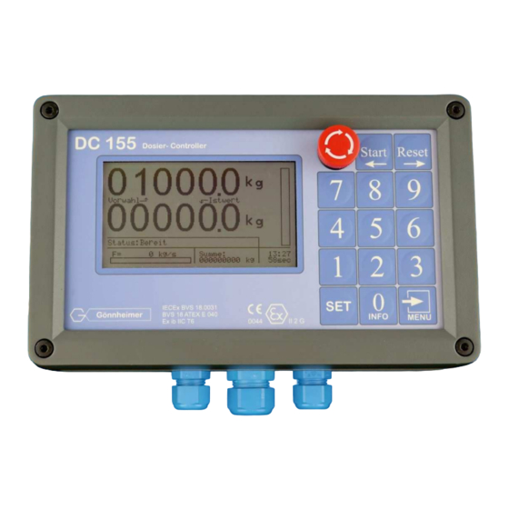
- Page 1 User's manual Dosing- Controller DC 155 Manual DC155_v2.0.16.doc...
-
Page 2: Table Of Contents
Page 2 1 safety guidelines DC155 Table of Contents OPERATION INSTRUCTION FOR EXPLOSION PROTECTED CONTROL PANELS ........3 INTRODUCTION: DOSING - CONTROLLER DC155 ................... 4 Short description ................................4 Basics ................................... 5 2.2.1 Units for preset, sum counter and flow ............................5 2.2.2 Impulse value, analogous input scaling............................5 Dosing applications .............................. -
Page 3: Operation Instruction For Explosion Protected Control Panels
DC155 1 safety guidelines Page 3 1 Operation instruction for Explosion protected control panels Application and Standards This instruction manual applies to explosion protected control panels of type of protection types below. This apparatus is only to be used as defined and meets re- quirements of EN 60 079 particularly EN60 079-14 "electrical apparatus for poten- tiality explosive atmospheres". -
Page 4: Introduction: Dosing - Controllerdc155
Page 4 2 Introduction DC155 DC155 2 Introduction: Dosing - controllerDC155 The following chapter 2 shows the whole functionality of the DC155, sorted by subject. Important hints for mounting, installation and starting are introduced in chapter 3. A short intro for structuring and parameter input of the DC155, as well as the complete functionality of the front keys and the display can be found in chapter 4. -
Page 5: Basics
DC155 2 Dosing controller DC155 Page 5 2.2 Basics 2.2.1 Units for preset, sum counter and flow The first step to configure the DC155 is to define the physical unit for preset, sum counter and flow. There- fore sufficient unit symbols are implemented into the DC155 (e.g. gram (g), kilogram (kg), tons (t), liter (l) etc.) To define the flow several time units are available. - Page 6 Page 6 2 Introduction DC155 DC155 Beside it is possible to define a maximum preset, to allow only equal or smaller presets to be set. The DC155 has three free programmable digital outputs. In the example above two of them must be re- served for valve control.
-
Page 7: Dosing Control With Proportional (Analogous) Valve
DC155 2 Dosing controller DC155 Page 7 Function Description (definition: output in normal open connection) 1. Counter = 0 The digital output is closed, if the actual value is equal to zero. Otherwise the digital is the digital output open. 2. - Page 8 Page 8 2 Introduction DC155 DC155 Preset Actual value 100 % Proportional- valve End value Start value of the falling ramp of the rising ramp Report: batch process is running time Pause time Start Stop Start expired Lag quantity Preset1 Preset 2 Preset You can configure the analogous output to a 0 ..20 mA or to a 4 ..20 mA signal.
-
Page 9: Simultaneously Flow And Batch Control (Option)
DC155 2 Dosing controller DC155 Page 9 Function Description (definition: output in normal open connection) 1. Flow prop. signal The analogous output is proportional to the actual flow 0/3 mA = 0 l/s; 20 mA = max. flow. Define max flow in the input menu 2. -
Page 10: Temperature Compensation (Requires Pt100- Option)
Page 10 2 Introduction DC155 DC155 2.5 Temperature compensation (requires Pt100- option) Any fluid has a specific expansion coefficient γ, i.e. in general, the volume of the fluid increases with its temperature. So using a volume measurement sensor for a mass dosing application, introduces an inaccu- racy into the dosing process, if the temperature changes. -
Page 11: Flow Monitoring
DC155 2 Dosing controller DC155 Page 11 2.6.2 Flow monitoring Flow fluctuations are considerable disturbances particularly if a reactor will be filled simultaneously with several substances or the flow exceeds the flow sensor limits. The DC155 can monitor min and max flow limits. If flow exceeds limits, the DC155 interrupts the batch process after a programmed time delay and indicates the disturbance on the display. -
Page 12: Code Words
Page 12 2 Introduction DC155 DC155 2.7.1 Code words The competence to enter or manipulate configuration or parameter settings are divided into 3 safety levels: 1. The lowest level is the competence to change the preset. The authorised persons, who know the code word 'preset' are able to change the preset not more. -
Page 13: Modbus (Option)
DC155 2 Dosing controller DC155 Page 13 Instruction code Function ESC 0 Request for counter (present value) state ESC S START- instruction ESC P STOP- instruction ESC Z RESET- instruction ESC K1 Enable keys ESC K0 Lock keys ESC B PRESET Set preset (e.g. -
Page 14: Calibrated Version, Batch Result Print Out
Page 14 2 Introduction DC155 DC155 • After writing a new preset into the registers 40002 and 40003, the DC155 will take the new preset at the next dosing process (not to the running dosing process). b) Functions The DC155 supports the Modbus functions below: Function number Function Read Holding Registers... -
Page 15: Additional Settings On Dc155
DC155 2 Dosing controller DC155 Page 15 2.9.5 Additional Settings on DC155 a) Menu blocking of the calibrated DC155 The menu of the DC155 must be protected against unauthorised manipulation especially by calibrated proc- ess. For this reason there must be a cable bridge inside of the DC155 to enter the menu of the DC155. To enter structure menu must the correct code word be entered and put a wire bridge between terminal 3 and 16... -
Page 16: Scale Signal Amplifier Connection
Page 16 2 Introduction DC155 DC155 2.10 Scale signal amplifier connection The combination of the dosing controller DC155 and the scale signal amplifier WV157 is a dosing system which works with a scale signal in hazardous area. The personnel starts the batch per „start“ key on the DC155. -
Page 17: Scale Calibration
DC155 2 Dosing controller DC155 Page 17 4. Koeff. cal. Choose “Yes” If you have the parameters of the load cell shown below. If not choose “No” and make a calibration 5. Max. load cell Maximum weight of the load cell 6. -
Page 18: Installation And Connection
Page 18 3 Installation and connection DC155 3 Installation and connection 3.1 Mounting The DC155 is dedicated for mounting and working in hazardous area zone 1. Please use the 4 holes on the rear plate for mounting and use a solid base. Observe local safety guidelines and the regulative VDE DIN 57 165 See hole distances below:... -
Page 19: Terminal Description Dc155
DC155 3 Installation and connecting Page 19 3.2.1 Terminal description DC155 Terminal Description 1,2 + Power supply input 5,6 - Power supply input/ Option: separate power supply for analogous ouput supply output for NAMUR- Sensors Connect only to a NAMUR sensor supplied on terminal 4 Input for 24V impulses Connect only to a NAMUR sensor supplied on terminal 4 10 +... -
Page 20: Sensor Terminals
Page 20 3 Installation and connection DC155 3.2.3 Sensor terminals a) 24V Impulses passive b) 24V Impulses active c) NAMUR- Signal d) 4-20 mA Signal Gönnheimer Elektronic GmbH phone.: +49 (6321) 49919-0, fax: -41 Email: info@goennheimer.de... -
Page 21: Actor Terminals
DC155 3 Installation and connecting Page 21 e) Pt100 terminal (4-wire connection) (NB: a Pt100 3-wire connection is not possible) 3.2.4 Actor terminals a) Digital outputs b) Analogous 0/4-20 mA output 3.2.5 TTY- interface Gönnheimer Elektronic GmbH phone.: +49 (6321) 49919-0, fax: -41 Email: info@goennheimer.de... -
Page 22: Power Supply Of Dc155
Page 22 3 Installation and connection DC155 3.3 Power supply of DC155 3.3.1 Application inside hazardous area The DC155 needs an intrinsically safe power supply with the maximal values of U = 30 V, I = 160 mA. The power consumption of the DC155 depends on the kind and count of additional options. The basic power consumption of the DC155 (Type code = DC155.x.0.0.x.0.0.x) is about 300 mW. -
Page 23: Reset
DC155 3 Installation and connecting Page 23 Impulse value 1.00000 l Max. flow 10.00 l/s output Dig. output 1 No function Dig. output 2 No function Dig. output 3 No function Dig. output 1 normal closed Alternative Dig. output 2 normal closed Normal open Dig. -
Page 24: Keyboard
Page 24 4 manual DC155 4.2 Keyboard The DC155 contents 14 keys and a STOP- switch, for complete configuration, parameter changing and manual operation. The functions of any key are listed below. Name State Function STOP- 1. During dosing process Valves are closed immediately, dosing proc- Switch ess is interrupted... -
Page 25: Parameter Input And Configuration
DC155 4 manual Page 25 2. While running menu Select menu item X 3. While figure input Choosing the figure X 4.3 Parameter input and Configuration It is not necessary to read the following section, if you want to go ahead quickly. The configuration of the DC155 is divided into 3 categories. - Page 26 Page 26 4 manual DC155 Gönnheimer Elektronic GmbH phone.: +49 (6321) 49919-0, fax: -41 Email: info@goennheimer.de...
-
Page 27: Annex
DC155 5 Annex Page 27 5 Annex 5.1 Block diagram DC155 Figure 6 block diagram DC155 Gönnheimer Elektronic GmbH phone.: +49 (6321) 49919-0, fax: -41 Email: info@goennheimer.de... -
Page 28: Technical Details
Page 28 5 Annex DC155 5.2 Technical Details Dosing controller DC155 General Mounting Inside hazardous area Ex-protection E Ex ib IIC T6 Housing protection class IP65 Mounting Ambient temperature -10°C ...+45°C at T6 -10°C ...+65°C at T4 Housing Dimensions H x B x T: 160 mm x 260 mm x 112 mm Material Aluminium lacquered / front foil: polyester Electrical... -
Page 29: Ex- Safety) Terminal Maximum Ratings
DC155 5 Annex Page 29 5.4 (Ex- safety) terminal maximum ratings Inputs terminal voltage current Power Comment 160mA 2,5W 2nF, 5µH power supply for DC155 1, 2 160mA 2,5W 2nF, 5µH power supply for DC155or analogous output Connect only to a NAMUR sensor in combination with terminal 4 160mA 5µH Input for voltage impulses... -
Page 30: Documentation Table
Page 30 5 Annex DC155 5.5 Documentation table 1.Category 2. Category Parameter value / choice Comment language German English French Dutch Structure Units preset 0 0 0 0 0 0 sum counter 0 0 0 0 0 0 0 0 0 flow 0 0 0 0 0 0 Batch control with abso-... - Page 31 DC155 5 Annex Page 31 Parameter Presets preset preset 1 preset 2 lag quantity Max. preset PID controller desired flow rate Analogous output Maximum value Start value rising ramp End value falling ramp Flow monitoring min. flow max. flow delay flow monitoring delay for Q<Qmin delay for Q>Qmax Pause time...
- Page 39 EG-Konformitätserklärung Declaration of conformity / Déclaration de conformité Communauté Européenne Anbieter: Gönnheimer Elektronic GmbH Supplier: Fournisseur: Gewerbegebiet Nachtweide Anschrift: Dr.-Julius-Leber-Straße 2 Address: Adresse: 67433 Neustadt/Weinstraße DC155, Produkt: Dosiercontroller Product: Produit: Das oben beschriebene Produkt erfüllt die Schutzanforderungen der folgenden EG-Richtlinien / the product described above complies with the following EG- rules / le produit décrit ci- dessus accomplit CU- réglementations 89/336/EWG, 93/68/EWG, 94/9/EG...
Need help?
Do you have a question about the DC 155 and is the answer not in the manual?
Questions and answers