Table of Contents
Advertisement
Quick Links
Advertisement
Table of Contents

Related Manuals for Gonnheimer Elektronic DC 155

Summary of Contents for Gonnheimer Elektronic DC 155
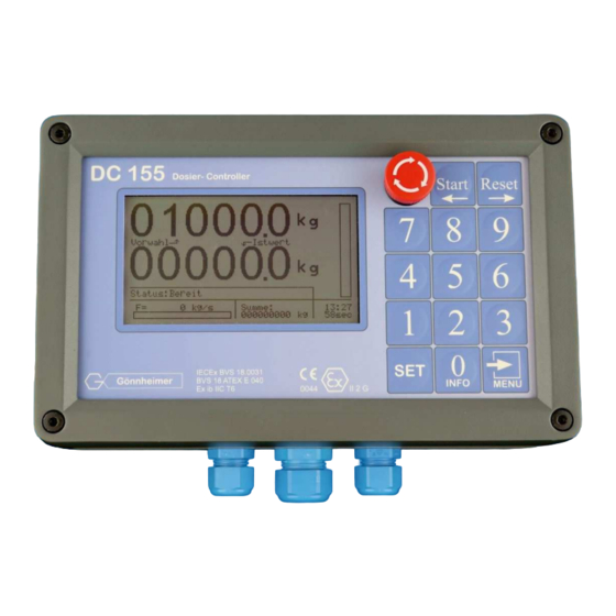
- Page 1 User's manual Dosing- Controller DC 155 Manual DC155 Rev.C03...
-
Page 2: Table Of Contents
Page 2 1 safety guidelines DC155 Table of Contents OPERATION INSTRUCTION FOR EXPLOSION PROTECTED CONTROL PANELS ........3 Application and Standards ............................3 General Instructions ..............................3 Before using the device ..............................3 Intrinsically Safe Circuits ............................. 3 INTRODUCTION: DOSING CONTROLLER DC155 ....................4 Short description ................................ -
Page 3: Operation Instruction For Explosion Protected Control Panels
DC155 1 safety guidelines Page 3 1 Operation instruction for Explosion protected control panels 1.1 Application and Standards This instruction manual applies to explosion protected control panels of type of protection types below. This apparatus is only to be used as defined and meets requirements of EN 60 079 particularly EN60 079-14 "electrical apparatus for potentiality explosive atmospheres". -
Page 4: Introduction: Dosing Controller Dc155
Page 4 4 manual DC155 2 Introduction: Dosing controller DC155 2.1 Short description The dosing controller DC155 is an all-purpose dosing control device to manage batch controlling of any arbitrary liquids or solid products inside the hazardous area. Advantages of this device are: •... -
Page 5: Dosing Applications
DC155 4 manual Page 5 2.3 Dosing applications Generally, a batch control system content a flow measuring, one or two valves and the batch controller. The flow sensor measures the quantity of the product per time, which flows into the target bowl and sends this information to the batch controller. - Page 6 Page 6 4 manual DC155 The DC155 has three free programmable digital outputs. In the example above two of them must be reserved for valve control. The polarity of each output can be configured as "normally open" or "normally closed". The following figure shows any possible function of a digital output.
-
Page 7: Dosing Control With A Proportional (Analog) Valve
DC155 4 manual Page 7 2.3.2 Dosing control with a proportional (analog) valve The DC155 can optionally get supplied with a 4...20 mA analog output to control a proportional solenoid valve. In this case, the analog output has to be configured as "Ramp shape". It is possible to set the maximum value of the analog output, the starting value and the ending value by using the following three parameters (percentage values): "Limit for analog output", "Start value of the rising ramp"... -
Page 8: Flow Controlled Dosing (Option Pid)
Page 8 4 manual DC155 Any alternative functions for the analog output are shown below: Settings for analog output: 0. No function 1. Flow prop. signal 2. Ramp shape 3. Flow feedback control 4. Counter prop. signal 5. Counter (max) prop. signal 6. -
Page 9: Batch Control With Absolute Level Signal (Requires 4
DC155 4 manual Page 9 2.3.4 Batch control with absolute level signal (requires 4...20mA analog input option ) This kind of batch control does not work with a flow signal, but with an absolute level signal. You can either measure the level in the container that is being filled (level rises during dosing) or the level of the container from which the material to be dosed is removed (level falls during dosing). -
Page 10: Temperature Compensation (Requires Pt100- Option)
Page 10 4 manual DC155 2.5 Temperature compensation (requires Pt100- option) Any fluid has a specific expansion coefficient γ. The volume of the fluid increases with its temperature. Using a volume measurement sensor for a mass dosing application, introduces an inaccuracy into the dosing process, if the temperature is not taken into account. -
Page 11: Process Monitoring
DC155 4 manual Page 11 You can see whether the temperature is within the permitted range in the lower right corner of the display: Dosing process Pt100-temperature Pt100-Temperatur inside permitted range outside permitted range not running "Temp: Measured Value °C" "Err: Measured Value °C "... -
Page 12: Safety
Page 12 4 manual DC155 Flow The general delay t starts on the beginning of the dosing process. No Flow monitoring takes place during this time. Afterwards selective delays (t and t ) start at the moment the flow exceeds its limits. If the flow doesn't return while the selective delay time is running, the DC155 interrupts the dosing and indicates the error on the display. -
Page 13: Key Locking
DC155 4 manual Page 13 configuration, key blocking) as well as changing code words. The factory setting of this access code "0003". Entering the structure menu access code cannot get disabled by setting the access code to "0000". The highest safety level is dedicated to plant engineers. 2.7.2 Key locking In some applications the DC155 is controlled using a decentralized control system (DCS) with no need for manual control. -
Page 14: Modbus (Option)
Page 14 4 manual DC155 Receiving a "ESC Z" instruction , the DC155 answers with a complete batch protocol print (date, time, quantity setpoint, filled quantity), if the feature "print protocol" has been enabled (Menu/structure/TTY in- terface). a) Print out format [info text] [date] [time]... -
Page 15: Operation Manual
DC155 4 manual Page 15 The read only bits in the Register 40001 are ignored when writing to this register. The registers 40002 and 40003 must be written simultaneously by using the modbus function 16 "Preset Multiple Registers". b) The DC155 supports the following modbus functions: Function number Function Read Holding Registers... -
Page 16: Keyboard
Page 16 4 manual DC155 3.2 Keyboard The DC155 has 14 keys and a STOP- switch, for complete configuration, parameter changing and manual operation. The functions of these keys are listed below. Name State Function STOP- 1. During dosing process Valves are closed immediately, Switch dosing process is interrupted... -
Page 17: Parameter Input And Configuration
DC155 4 manual Page 17 3.3 Parameter input and Configuration It is not necessary to read the following section, if you want to go ahead quickly. If you start the parameter or the structure menu while a dosing pro- cess is running, the dosing is stopped immediately: the valves close, the actual value is reset to "0". - Page 18 Page 18 4 manual DC155 Gönnheimer Elektronic GmbH phone.: +49 (6321) 49919-0, fax: -41 Email: info@goennheimer.de...
-
Page 19: Starting, Parameter Default Settings
DC155 5 Annex Page 19 4 Starting, parameter default settings The following table shows the parameter settings defaults. These basic defaults exist on each DC155. The parameter count can increase by any additional option. 1. Level 2. Level Parameter Value Comment Language German, English, French,... -
Page 20: Reset
Page 20 5 Annex DC155 1. Level 2. Level Parameter Value Comment Parameter Setpoints Max. Setpoint 999999 kg Setpoint 0 kg Setpoint 1 0 kg Setpoint 2 0 kg Lag quantity 0 kg Flow monitoring Minimum Flow 0 kg/s only visible, if Flow Control has been Maximum Flow 0 kg/s activated in the structure menu... -
Page 21: Power Supply Of The Dc155
DC155 5 Annex Page 21 6 Power supply of the DC155 6.1.1 Application inside hazardous area The DC155 needs an intrinsically safe power supply with the maximal values of U = 30 V, I = 160 mA. The power consumption of the DC155 depends on the kind and count of additional options. The basic power consumption of the DC155 (Type code = DC155.x.0.0.x.0.0.x) is about 300 mW. -
Page 22: Dc155 For Safe Area Application
Page 22 5 Annex DC155 6.1.2 DC155 for safe area application If you use the DC155 for safe area applications and do not wire the DC155 into hazardous areas, then you can supply the DC155 directly by a 24VDC net. In that case, there is no separate power supply device nec- essary. -
Page 23: Panel Mounting
DC155 5 Annex Page 23 7.1.1 Panel Mounting 7.2 Electrical Wiring The regulations of IEC/EN 60079-14 and the EU type examination certificate IECEx BVS 18.0031 / BVS 18 Warning ATEX E 040 must be observed. The intrinsically safe terminal limits must be observed. The intrinsically safe terminal limits are included in the EU type ex- Warning amination certificate BVS 18 ATEX E 040 / IECEx BVS 18.0031... -
Page 24: Terminal Description Dc155
Page 24 5 Annex DC155 7.2.1 Terminal description DC155 Terminal Description 1,2 + Power supply of DC155 5,6 - Power supply of DC155 / Option: separate power supply for analog output and/or TTY/RS485 interface, respectively. Supply output for NAMUR- Sensors Connect only to a NAMUR sensor supplied by terminal 4 Input for 24V impulses Connect only to a NAMUR sensor supplied by terminal 4... -
Page 25: Power Supply
DC155 5 Annex Page 25 7.2.2 Power supply a) Standard b) Separate power supply of analog output and TTY / RS485 7.2.3 Sensor terminals a) 24V Impulses passive b) 24V Impulses active Gönnheimer Elektronic GmbH phone.: +49 (6321) 49919-0, fax: -41 Email: info@goennheimer.de... -
Page 26: Actor Terminals
Page 26 5 Annex DC155 c) NAMUR- Signal d) 4-20 mA Signal e) Pt100 terminal (4-wire connection) (2-wire connection) (NB: a Pt100 3-wire connection is not possible) 7.2.4 Actor terminals a) Digital outputs b) Analog 0/4-20 mA output Gönnheimer Elektronic GmbH phone.: +49 (6321) 49919-0, fax: -41 Email: info@goennheimer.de... -
Page 27: Tty Interface
DC155 5 Annex Page 27 7.2.5 TTY interface 7.2.6 RS485 interface Gönnheimer Elektronic GmbH phone.: +49 (6321) 49919-0, fax: -41 Email: info@goennheimer.de... -
Page 28: Annex
Page 28 5 Annex DC155 8 Annex 8.1 Block diagram DC155 Figure 5 block diagram DC155 Gönnheimer Elektronic GmbH phone.: +49 (6321) 49919-0, fax: -41 Email: info@goennheimer.de... -
Page 29: Technical Details
DC155 5 Annex Page 29 8.2 Technical Details Dosing controller DC155 General Mounting Inside hazardous area Ex-protection 2 II G Ex ib IIC T6 Gb EU type examination BVS 18 ATEX E 040 certificate IECEx BVS 18.0031 Housing protection class IP65 Mounting Ambient temperature... -
Page 30: Type Code (Configuration Example)
Page 30 5 Annex DC155 8.4 Type Code (Configuration example) DC155 .x .x .x .x .x .x .x Analog input: No analog input One 4...20mA input Analog output: No analog output 0/4...20mA output PID controlled analog output NAMUR input: NAMUR input Two NAMUR inputs Pt100 input: No Pt100 input... -
Page 31: Documentation Table
DC155 5 Annex Page 31 8.7 Documentation table This documentation table is complete, but not without contradictions. Not all parameters can be entered at the same time as they are listed next to each other in the table, since some parameters only appear in certain configurations. Simply ignore the unused parameters or cross them out. - Page 32 Page 32 5 Annex DC155 1. Level 2. Level Parameter Value / Choice Comment Structure Outputs 0 No Function analog 1 Flow prop. signal 2 Ramp shape 3 Flow feedback control 4 Counter prop. signal 5 Counter (max) prop. signal 6 Setpoint prop.
- Page 33 DC155 5 Annex Page 33 1. Level 2. Level Parameter Value / Choice Comment Codes Code for setpoint Code for parameter menu Code for structure menu Gönnheimer Elektronic GmbH phone.: +49 (6321) 49919-0, fax: -41 Email: info@goennheimer.de...
Need help?
Do you have a question about the DC 155 and is the answer not in the manual?
Questions and answers