Table of Contents
Advertisement
Quick Links
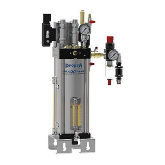
MaXtreme
Processing with a minimum quantity
aerosol lubrication
Manual drafted in compliance
with directive 2006/42
DropsA products can be purchased at DropsA branches and authorised distributors,
Operation and maintenance manual
Original instructions
go to www.dropsa.com/contact or write to sales@dropsa.com
C2314IE WK 19/20
1
Advertisement
Table of Contents

Related Manuals for DROPSA MaXtreme

Summary of Contents for DROPSA MaXtreme
- Page 1 Processing with a minimum quantity aerosol lubrication Operation and maintenance manual Original instructions Manual drafted in compliance with directive 2006/42 C2314IE WK 19/20 DropsA products can be purchased at DropsA branches and authorised distributors, go to www.dropsa.com/contact or write to sales@dropsa.com...
-
Page 2: Table Of Contents
9.1 REMOVAL OF THE PRESSURE RESIDUE ....19 3.2 AIR QUALITY ............8 9.2 EXTERNAL CLEANING OF THE EQUIPMENT ..19 3.3 LUBRICANT: MAXTREME OIL ....... 8 9.3 CLEANING THE INSIDE OF THE EQUIPMENT ..19 3.4 PRESSURE ............10 10. -
Page 3: Introduction
"through the tool". Internal lubrication is the most difficult to achieve due to the coalescence of oil particles inside the tool. MaXtreme solves this by generating ultra-thin particles that can pass through the rotating tool without hindrance caused by centrifugal force. -
Page 4: System Operation Summary Table
1.3 SYSTEM OPERATION SUMMARY TABLE PRESSURE OPERATING CONDITIONS VORTEX 1 VORTEX 2 EXTRA AIR AEROSOL DENSITY TANK ΔPress. >1<=2 NORMAL TOOLS NORMAL NORMAL ΔPress. >2 BIG TOOLS ΔPress.=1 SMALL MEDIUM TOOLS NORMAL HIGH NORMAL ΔPress.<1 SMALL TOOLS HIGH HIGH ΔPress = supply pressure - tank pressure 1.3.1 MULTIPLIER ON/OFF TANK PRESSURE DURING AIR SUPPLY PRESSURE... -
Page 5: Structure And Operation
2. STRUCTURE AND OPERATION 2.1 LP/HP CIRCUIT OPERATION The system consists of a pressurised lubricant reservoir with air. The lubricant contained in the tank (1) is sent through a pipeline inside the tank itself, to the generator nozzle (3) located inside the generator head, as a result of the pressure from the air, regulated by the valve (2). - Page 6 Hydraulics diagram Vortex Operation (LP) Vortex (HP) operation from pneumatic pilot valve Scheme 1 Scheme 2 Piloting (LP/HP) with solenoid valve Scheme 3...
- Page 7 3. Use safety and precautions Before carrying out any operation it is important to read this manual. It is always recommended to respect the safety standards of the country where the equipment is installed and the need to resort to personnel specialised In the various maintenance, use, installation, etc.
-
Page 8: Materials Present On The System
During operation, the system has been designed to use specific products for production purposes, i.e. the lubricants contained in the tank are used to carry out its activity. The only lubricant permitted by the manufacturer DropsA S.p.A. is a non-hazardous mixture according to the agreement (EC)1272/2008 [GHS] as described on its MSDS... - Page 9 Use on ferrous and non-ferrous materials In case oils other than those recommended by DropsA S.p.A. are used, they must belong to group 2 according to the PED Directive, and must be a non-hazardous mixture according to agreements (EC)1272/2008 [GHS], with the...
-
Page 10: Pressure
3.4 Pressure CAUTION Before each intervention check the absence of residual pressures in each branch of the lubricant circuit. After long periods of inactivity, check the seal on all the parts subject to pressure. Do not subject the fittings, pipes and the parts under pressure to violent impact. A damaged hose or fitting is DANGEROUS, replace it. -
Page 11: Technical Characteristics
Air supply hose: Ø12mm.(0.47 in) Usage tube: Ø12 ÷ 16 mm (0.47 ÷ 0.6 in.) Number of aerosol outlets: Lubricant DropsA recommends MaXtreme OIL for the best results Degree of protection: IP 65 Electro-pneumatic valve power supply: 24VDC200mA (Optional) Operating temperature 0°C ÷... -
Page 12: Equipment Components
6. EQUIPMENT COMPONENTS Safety valve High flow nozzle Solenoid valve HP/LP high/low-pressure piloting 6 bar (optional Valve Pressure relief valve non-return tank Tank pressure gauge Port of use free Network pressure regulator unit Quick connect ø12 (optional) Slide valve On/Off HP nozzle 20 bar Air inlet Filling port... -
Page 13: Unpacking And Installation Of The Machine
Place the equipment on the machine vertically and in an easily accessible location. NEVER flip the equipment The operator is responsible for any damage caused to the MaXtreme equipment by improper installation. 7.2.2 COMPRESSED AIR CONNECTION WARNING The compressed air connection must be made by competent and qualified personnel. -
Page 14: First Filling
7.2.3.2 SUBSEQUENT FILLINGS When the oil reaches the "minimum" level (A), MaXtreme must be refilled. If the unit is in operation, switch it off and eliminate the residual pressure (Ref.par.9.1). Then proceed as described in 7.2.3.1 FIRST FILLING UP. -
Page 15: Pipes And Nozzles
8. OPERATING INSTRUCTIONS The same general procedures and precautions typical of the installation of traditional lubrication and cooling systems must be observed. 8.1 MaXtreme SETTINGS Refer to the figure in paragraph 6 Air quantity: by air pressure regulator with pressure gauge. -
Page 16: Internal Lubrication
8.3 INTERNAL LUBRICATION MaXtreme is used for internal lubrication work: the aerosol is brought inside the tool via the spindle. In such a situation, it is suggested to follow the following instructions: The spindle must be suitable for the type of application in question (dry machining). - Page 17 TANK PRESSURE (bar) HIGH AIR/OIL FLOW RATE PRESS 20 BAR VORTEX 2 OIL FLOW RATE (CC/H) AIRFLOW (Nm3/H) TANK PRESSURE (bar) *not applicable to MaXtreme one COMBINED AIR/VORTEX OIL FLOW RATE OIL FLOW RATE (CC/H) AIRFLOW (Nm3/H) TANK PRESSURE (bar) *not applicable to MaXtreme one Maxtreme oil viscosity: <50cSt 40°...
-
Page 18: Electrical Connections Minimum Level
Below is a troubleshooting table highlighting the main failures, probable causes and possible solutions. If, even after consulting the diagnostic table, the problem has not been solved, do not proceed with troubleshooting by disassembling parts of the machine, but contact the Technical Office DropsA and report the anomalies found with a detailed description. -
Page 19: Maintenance Procedures
Open the quick exhaust valve on the head, making sure that the pressure gauge marks "0" bar. Open the quick exhaust valve on the circuit at 20 bar. 9.2 EXTERNAL CLEANING OF THE EQUIPMENT MaXtreme Cleaning Eliminate residual pressure. (Par. 9.1) ... -
Page 20: Disposal
See local regulations for their correct disposal. Upon dmolition of the machine, the identification label and any other document must be destroyed. 11. ORDER INFORMATION Part number Description 3135263 Maxtreme -1 with minimum level, single nozzle (HP circuit deactivate) 3135264 Maxtreme - with minimum double-level nozzle Accessories Part number Description... -
Page 21: Double Pneumatic/Electric Control Nozzle
12.2 DOUBLE PNEUMATIC/ELECTRIC CONTROL NOZZLE Dimensions in mm (inches) 570 (22.5) 292 (11.5) 170 (6.69) 232 (9.1) 439 (17.28) 97 (3.81) 120 (4.72) 140 (5.51) 157 (6.18) TUBO ø12 / NIPPLO G1/2”... -
Page 22: Transfer And Transportation
13. TRANSFER AND TRANSPORTATION Before shipment, the unit is carefully packed in a cardboard box. Upon receipt, check the packaging for damage and store the equipment in a dry place. NOTICE Machine components can withstand temperatures, during storage, from -10 to +80 °C; In order to avoid damage, the machine must be started when it has reached a temperature of 0 °C. -
Page 23: Contraindications Of Use
Inappropriate Posture: The correct overall dimensions and the installation methods are indicated in this manual. Use of unsuitable lubricant: the characteristics of the lubricant can be found both on the unit and on this User and Maintenance Manual (in case of doubt, please contact DropsA S.p.A. the Technical Department... -
Page 24: Copyright
Contraventions shall be liable for damages. Reprints, even of extracts, are only permitted with the approval of DropsA S.p.A. We reserve the right to implement technical modifications to the machine at any time in order to improve safety, reliability, function and design.
Need help?
Do you have a question about the MaXtreme and is the answer not in the manual?
Questions and answers