Table of Contents
Advertisement
Quick Links
●
Thank you for purchasing our product. This product is a multifunction meter and is easy to install. Before using, please read the instructions
carefully and retain them for future reference.
Attention!
● For installation, please follow the steps described. Any damage caused by wrong installation shall be imputed to the users.
● To avoid a short circuit from occuring do not pull or modify the wires during installation.
● Do not disassemble or change any parts. Opening and dissassembling this unit will void any warranty.
● Maintenance and repairs should be executed by our professionals only.
◎ Symbol description:
NOTE
Some procedures must be followed to avoid damages to the instrument.
WARNING!
Certain procedure must be followed to avoid damages to yourself, to the vehicle or others.
1-1 Accessories
1
LCD meter X1
6
Velcro X1 set
2-1 Wiring Installation Instructions
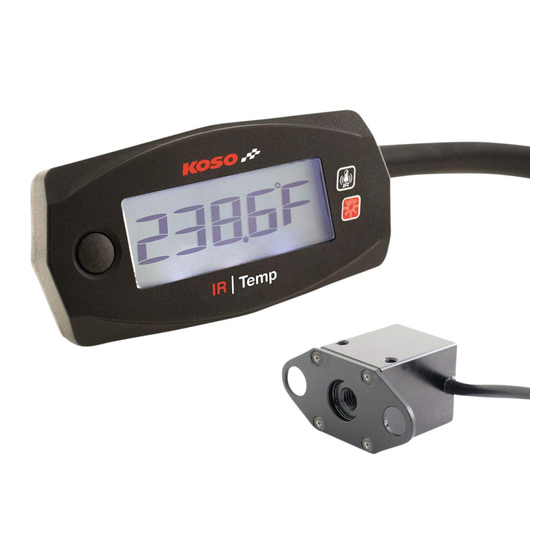
IR
/ Temp
LCD meter(Accessory 1)
2-2 Installation Instructions
4.
2.
1.
3.
A
2
3
Meter cover X1
IR
/ Temp
7
8
Infrared temp sensor X1
Power wire
Temp sensor wire
Follow the steps below during
installation.
1.LCD meter(Accessory 1)
A
2.M3 X L20 screw(Accessory 5-A)
2.
3.M3 X P0.5 nut(Accessory 5-B)
4.Meter cover(Accessory 2)
1.LCD meter(Accessory 1)
B
1.
2.Meter cover(Accessory 2)
3.Velcro-male(Accessory 6)
4.Velcro-female(Accessory 6)
3.
NOTE
4.
B
4
Temp sensor wire X1
9
Bolted cover X1
Mid-way connector
Black / Ground wire connect to the vehicle body or
the engine. (it must be a good ground)
(Accessory 4)
(Accessory 3)
Infrared temp sensor(Accessory 7)
Choose either Method A or B
according to your need.
M3 X L20 screw X2(A)
5
Power wire X1
M3 X P0.5 nut X2(B)
M2x5LxP0.4 screw X6(A)
10
1.3 mm Allen key X 1
M3X5XP0.5 screw X2(B)
(A)
(B)
Red / "+"Wire connect key on
DC 12V main power switch
Infrared Temp Sensor
2-3
Installation Instructions
A
3.
2.
1.
(May install in the
front and the back.)
Follow the steps below during installation.
1.Infrared temp sensor(Accessory 7)
A
2.Bolted cover(Accessory 8)
3.M2x5LxP0.4 screw(Accessory 9-A)
1.Infrared temp sensor (Accessory 7)
B
2.M3X5XP0.5 screw(Accessory 9-B)
NOTE
Choose either Method A or B according to your need.
The screw hole concaves are the fixing place for the
bolted cover(Accessory 8).
FLASH
LIGHT ON
HOLD THE
HOLD THE
BUTTON ONE
BUTTON 3
SECONDS
SECONDS
(B)
(A)
B
1.
2.
(May install in the
right and the left.)
wh033ba26c
Advertisement
Table of Contents

Related Manuals for Koso BA033050

Summary of Contents for Koso BA033050
- Page 1 ● Thank you for purchasing our product. This product is a multifunction meter and is easy to install. Before using, please read the instructions carefully and retain them for future reference. Attention! ● For installation, please follow the steps described. Any damage caused by wrong installation shall be imputed to the users. ●...
- Page 2 Functions, Settings Description ● Temperature Display range : -4.0 ~ 302.0 ℉, Display unti : 0.1 ℉ ● Temperature warning Setting range : 140 ~ 302 ℉, Setting unit : 1 ℉ 34.4 ● Volt meter Display range : 8.0 v~18.0 v , Display unti : 0.1 v / Temp ●Effective voltage DC 12V...
- Page 3 Sensor description The sensor has a 10° wide operation angle. (creating a cone area) The distance from the sensor to the surface influences the reading area The reading area * To get a larger reading area, move the sensor away from the area ** To get a smaller...
Need help?
Do you have a question about the BA033050 and is the answer not in the manual?
Questions and answers