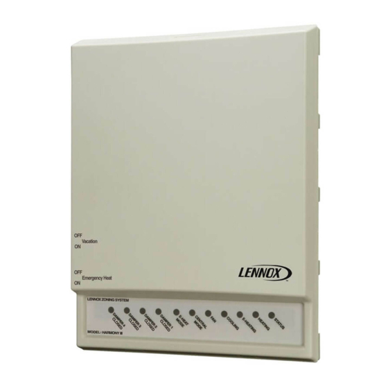
Lennox Harmony III Installation Instructions Manual
Zone control system
Hide thumbs
Also See for Harmony III:
- Installation, setup and user manual (80 pages) ,
- Installation instructions manual (60 pages) ,
- Manual (13 pages)
Table of Contents
Advertisement
Quick Links
E2006 Lennox Industries Inc.
Dallas, Texas, USA
RETAIN THESE INSTRUCTIONS
FOR FUTURE REFERENCE
Shipping & Packing List
Items shipped with the Harmony IIIt Zone Control System
include:
1 − Zone Control System circuit board
Additional items (ordered separately; see requirements on
Page 3) include:
Transformer
Dampers
Thermostats
(For Heat Pump Option)
Pressure switch: R−22 (21J18); R−410A (51M08)
04/06
*2P0406*
INSTALLATION
INSTRUCTIONS
Harmony IIIt Zone Control
System
ZONING
505,023M
04/06
Supersedes 01/06
Table of Contents
Shipping & Packing List
Introduction
Residential Zone Control System − Field Wiring
System Components
Separately-Ordered System Components
Install Heating and Cooling Equipment
Component Installation
Blower Speed Adjustment
Zone Control System Jumper Settings
Common System Component Wiring
Component Specific Wiring
®
and
Introduction
The Lennox Harmony IIIt Zone Control System manages
the distribution of conditioned air to specific areas or zones
in a house or small commercial building. The system di-
rects heated or cooled air to occupied areas without condi-
tioning unused areas. This control maximizes economy
while providing a balanced and comfortable environment.
The system can be used in any of the following Lennox
HVAC system application options:
1. Variable speed gas furnace and either a single− or two-
stage condensing unit.
2. Variable speed blower coil unit with electric heat and
either a single− or two-stage heat pump or air condi-
tioner.
3. Variable speed gas furnace and heat pump.
Variations on the options described above and included in
this document are: cooling−only, hot water coil, and cooling
system with electric heat applications.
Page 1
. . . . . . . . . . . . . . . . . . . . . . . .
. . . . . . . . . . . . . . . . . . . . . . . . . . . . . . . . . . .
. . . . . . . . . . . . . . . . . . . . . . . . . . .
. . . . . . . . . . . . . . . . . . . . . . . .
. . . . . . . . . . . . . . . . . . . . . .
. . . . . . . . . . . . . . . . . . . . .
. . . . . . . . . . . . . . . . . . . . . . . . . . . . .
. . . . . . . . . . . . . .
. . . . . . . . . . . . . . . . . . . . . . . . . . . . . . . . . .
. . . . . . . . . . . . . . .
. . . . . . . . . . . . . . . . . . . . . . . . . . . . . . .
. . . . . . . . . . . . . . . . . . . . . . . . . . . .
. . . . . . . . . . . . . . . . . . . . . .
. . . . . . . . . . . . . . . . . . . .
*P505023M*
Litho U.S.A.
1
1
. . . .
2
3
. . . . . . . . .
3
. . . . . . . . . . .
4
4
6
. . . . . . . . . . .
8
. . . . . . . . . . . . .
12
13
16
. . . . . . . . . . .
18
18
19
19
. . . . . . . . . . . . .
20
. . . . . . . . . . .
20
. . . . . . . . . .
21
. . . . . .
21
. . . . .
22
. . . .
22
25
25
27
30
505,023M
Advertisement
Table of Contents
Troubleshooting

Related Manuals for Lennox Harmony III


Summary of Contents for Lennox Harmony III
-
Page 1: Table Of Contents
This control maximizes economy while providing a balanced and comfortable environment. 1 − Zone Control System circuit board The system can be used in any of the following Lennox 1 − Discharge Air Sensor HVAC system application options: Additional items (ordered separately;... - Page 2 The Harmony IIIt zone control system uses off−the−shelf, When the system is in the zone control mode, a zone is single-stage, non-heat pump, non−power-robbing elec- conditioned only upon demand. All wiring connections to tronic thermostats and motorized dampers in any of the ap- the zone control board are made using low voltage, 18 plications to distribute conditioned air to different zones.
- Page 3 A pressure switch [R−22 (21J18); R−410A (51M08)] is re- Thermostats quired for applications with a Lennox heat pump (Options 2 For all zones, use thermostats that are of this type: and 3). The pressure switch acts as a guard in case of high electronic thermostat head pressures during first−...
-
Page 4: Important
Variable Speed Blower Motor (VSM) technology. hibits the heat pump from attempting to fill a demand for heat. 1. Lennox Blower Coil Unit with VSM Use ONLY blower coil units equipped with a variable speed blower motor; Balance Point Sensor... - Page 5 Install the discharge air temperature probe in the dis- Thermostats charge plenum downstream from the cooling coil. Be sure Locate each thermostat in its zone. If two or more rooms that the discharge air will pass over the sensor before the are within a single zone, place the thermostat in a location air is distributed into the duct system.
- Page 6 Blower Control Adjustment IMPORTANT Variable-speed furnaces and blower coil units are Be sure to cut jumper W914; if not cut, the zone con- equipped with a variable-speed control board. The blower trol board DS fuse will blow. motor speed must be adjusted to produce the zoning CFM requirements managed by the zone control system.
- Page 7 Variable-Speed Blower Unit − Jumper Settings BDC3 Board Cable Modifications Locate the BDC3 board in the blower control box. Jumper settings on the BDC3 board control the blower CFM. (LOOK FOR Before connecting the zone control board to the BDC3 RAISED NUMBERS ON BACK OF board, complete the following electrical adjustments.
- Page 8 Table 3 Zone Control Board Jumper Settings Air Jumper Positions Conversion Chart Setup is required to allow the zone control system to con- Model Equivalent Positions (%) trol equipment staging and deliver the proper amount of ® Harmony II CFM to the zones. Only qualified technicians should per- form equipment setups.
- Page 9 4. Set the air selection jumper for the zone using the per- When the zone control system is set for a particular zone, cent air determined in step 3. If the percent air falls be- heating reduction jumper, and/or continuous air reduction tween available jumper settings, select the nearest settings determine the total CFM available from the unit as unit of ten.
- Page 10 3. Determine heating PIAB and total heating air CFM 4. Determine total air delivered during a continuous delivered during a heating call Calculate these to- blower call Calculate these totals using the formu- tals using the formulas and example in Table 7. The ex- las and example (Table 8) which uses the same as- ample uses the following assumptions: sumptions as table 7, except with zones 1, 2 and 3 call-...
- Page 11 SYSTEM Configuration Jumper When using a heat pump with electric backup heat, insert an E−HEAT jumper to select the total number of available The SYSTEM configuration jumpers must be inserted to electric heat stages. Upper right-hand view in figure 14 select the type of cooling and heating system that has shows 1 heat-strip configuration.
- Page 12 II wiring limit of 75 VA. WIRING TRANSFORMER 24 VAC Combined load of zone dampers and zone relays not to exceed 60VA. ZONE Use Lennox Part 69J56 for Zone RELAY 1 Relays 1 through 4. EXTENDED ZONE 1 DAMPER ZONE 1...
- Page 13 Pressure Switch Wiring Component Specific Wiring Pull a two−wire thermostat cable from the field-installed Thermostat Wiring pressure switch to the zone control board and connect at Using standard electronic 1-heat /1-cool non-heat pump, the pressure switch, and at the zone control board as non-power robbing thermostats, and five−wire thermostat shown in the connection location diagram (see figure 20).
-
Page 14: Discharge Air Sensor
Harmony IIIt Zone Control System Option 1 − Lennox Variable-Speed Gas Furnace & Lennox 2-Stage Air Conditioner Thermostat 2 Thermostat 1 W C Y G R W C Y G R Thermostat 4 Thermostat 3 PS PS BPS BPS W C Y G R... - Page 15 Harmony IIIt Zone Control System Option 2 − Lennox Heat Pump & Lennox Variable-Speed Coil Blower PRESSURE SWITCH Thermostat 2 Thermostat 1 21J18 (R−22) W C Y G R W C Y G R 51M08 (R−410A Thermostat 4 Thermostat 3...
-
Page 16: Balance Point Sensor 56A83
Harmony IIIt Zone Control System Option 3 − Lennox Heat Pump & Lennox Variable-Speed Gas Furnace (Dual Fuel) Thermostat 2 Thermostat 1 W C Y G R W C Y G R PRESSURE SWITCH BALANCE POINT 21J18 (R−22) SENSOR 56A83 51M08 (R−410A) - Page 17 2. Fan On / Auto Mode Zone thermostats can send a Cooling Operation continuous fan signal to the zone control system. The When the Harmony IIIt zone control system receives a zone control system will signal the blower to supply air thermostat cooling call, the following events occurs: to zones calling for continuous fan while no other con- The zone control unit checks to make sure it has been...
-
Page 18: Operation & Troubleshooting Indicators
may be on) is turned off and continuous fan runs (if the System Indicators/Troubleshooting Devices demand for heat remains) until the air temperature falls below 130ºF and the minimum timed−off delay ex- pires. If the heat pump goes into defrost mode, the zone con- trol energizes all stages of compressor and the first stage of electric heat. -
Page 19: Time Delays
onds starting with the most recent code, then the next most which precede or follow a demand, depending on the type recent, and so on. Pressing the button while recalling fault of function. The delays are used to control equipment con- codes will bypass the 10-second timer and go right to the nected to the system. -
Page 20: Gas Heating Checkout − Single Zone
Gas Heating Checkout − Single Zone Prerequisites: 1. Set zone 1 thermostat for a heat demand; check: Zone 1 thermostat W LED on (heating demand). Zone 1 thermostat set to Heat Damper 1 LED off (damper open). Damper 2, 3, and 4 LEDs on (dampers closed). Output Heat W1 LED on (furnace on). -
Page 21: Gas Heating Checkout − Central Control
Gas Heating Checkout − Central Control Prerequisites: 1. Set zone 1 thermostat for a heat demand; check: Zone 1 thermostat W LED on (heating demand). Central mode switch on Output Heat W1 LED on (furnace on). Red LED on the central mode fan switch on Heating LED on. -
Page 22: Heat Pump Heating Checkout − Multiple Zone
Heat Pump Heating Checkout − Multiple Zone Prerequisites: Output Heat LED Y1 on (compressor). Heating and Fan LEDs on. All zone thermostats set to Heat LEDs dampers 1 − 4 off (all dampers open). Pressure Switch LED on. The compressor in the outdoor unit begins operating in the heating mode. - Page 23 Gas Heating Checkout − Single Zone − Dual Fuel Option and Balance Point Sensor (BPS) Prerequisites: 1. Set zone 1 thermostat for a heat demand; check: Zone 1 thermostat set to Heat Zone 1 thermostat W LED on (heating demand). Damper 1 LED off (damper open).
- Page 24 Gas Heating Checkout − Central Control − Dual Fuel Option and BPS Prerequisites: 1. Set zone 1 thermostat for a heat demand; check: Zone 1 thermostat W LED on (heating demand). Central mode switch on Output Heat W1 LED on (furnace on). Red LED on the central mode fan switch on Heating LED on.
-
Page 25: Troubleshooting
2. Establish a compressor heating demand and allow 0 volts DC = low speed or off. system to begin operating (see heat pump heating All speeds in between are a percentage of 22VDC. checkout section for details). Troubleshooting 3. Allow system to operate several minutes so refrigerant pressures can balance. - Page 26 Diagnostics Codes (0−off;1−on) Fail-safe Code Diag LED Fault (System 1234 Remedy Shut Down) Indicated 0010 Defrost while System detected defrost signal at W1−Def terminal block while the jump- gas heat er is selected for the furnace. May be caused by: selected Wrong selection for INDOOR UNIT jumper.
-
Page 27: Troubleshooting Diagrams
Troubleshooting Diagrams System Troubleshooting − Harmony IIIt Zone Control System Option 1 − Lennox Variable-Speed Gas Furnace and Lennox Condensing Unit Are thermostats wired correctly? Does zone control system respond appropriately to demand? Line Voltage to transformer? Heat/cool thermostat used? (Must not use heat pump thermostat.) - Page 28 System Troubleshooting − Harmony IIIt Zone Control System Option 2 − Lennox Heat Pump & Lennox Variable-Speed Coil Blower Pressure Switch installed. in cor- Are thermostats wired correctly? Line Voltage to transformer? rect position? Does zone control system respond appropriately to demand?
- Page 29 System Troubleshooting − Harmony IIIt Zone Control System Option 3 − Lennox Heat Pump & Lennox Variable-Speed Gas Furnace (Dual Fuel) Are thermostats wired correctly? Does zone control system respond appropriately to demand? Pressure Switch installed. in correct position? Line Voltage to transform-...
-
Page 30: Piab Calculation Worksheet
PIAB Calculation Worksheet PIAB = [(Required CFM − Minimum CFM) / (Maximum CFM − Minimum CFM)] * 100 Sample CFM ' Required Minimum Maximum Minimum Sample PIAB = [(___1020 − ) / ( 2200 − x 100 Sample PIAB = [( ) / ( 1500 x 100...
Need help?
Do you have a question about the Harmony III and is the answer not in the manual?
Questions and answers