Table of Contents
Advertisement
Quick Links
OWNER / OPERATOR MANUAL
WARNING
The engine exhaust from this product
contains chemicals known to the State
of California to cause cancer, birth
defects or other reproductive harm.
APPLICABLE SERIAL NUMBERS :
DRIVE UNIT 000000 and up
LONG REACH TRIMMER
LRTZ2500
CUTTING UNIT 000000 and up
WARNING
Before using our trimmers, please
read this manual carefully to
understand the proper use of your
unit.
ENGINE UNIT 000479 and up
T1503-93110(912)
Advertisement
Table of Contents

Related Manuals for RedMax LRTZ2500


Summary of Contents for RedMax LRTZ2500
- Page 1 State of California to cause cancer, birth defects or other reproductive harm. APPLICABLE SERIAL NUMBERS : DRIVE UNIT 000000 and up LRTZ2500 Before using our trimmers, please read this manual carefully to understand the proper use of your unit.
- Page 2 INFORMATION This machine is equipped with an Overload Cancellation Mechanism. When the cutting blades have got into metal wires or those twigs difficult to cut, the mechanism acts as a shock absorber, and protects the drive gears and the blades from severe reaction which could give damage to those parts.
-
Page 3: Table Of Contents
SAFETY FIRST Instructions contained in warnings within this manual marked with a critical points which must be taken into consideration to prevent possible serious bodily injury, and for this reason you are requested to read all such instructions carefully and follow them without fail. WARNINGS IN THE MANUAL WARNING This mark indicates instructions which must be... -
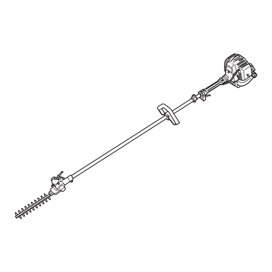
Page 4: Parts Location
1. Parts location 2. Specifications LRTZ2500 Overall size(LxWxH)························································ 90.1(2300)x9.8(250)x12.2(310) in(mm) Dry weight w/o acc. ···························································································· 13.4 (6.1) lbs(kg) Engine Type ········································································· Air-cooled 2-stroke gasoline Model ··························································································· Zenoah GZ25N Displacement ··········································································· 1.6cu-in (25.4cm Max. output ······················································· 1.2Hp (0.9kW)at 7500/min Idle speed ·············································································3000±200/min Fuel ···········································································... -
Page 5: Warning Labels On The Machine
WARNING Never modify your trimmer. We won't warrant the machine, if you use the remodeled trimmer or you don't observe the proper usage written in the manual. 4. Symbols on the machine For safe operation and maintenance, symbols are carved in relief on the machine. -
Page 6: For Safe Operation
5. For safe operation 1. Read this manual carefully until you completely understand and follow all safety and operating instructions. 2. Keep this manual handy so that you may refer to it later whenever any questions arise. Also note, if you have any questions which cannot be answered herein, contact the dealer from whom you purchased the product. - Page 7 5. For safe operation b. At night, at times of heavy fog, or at any other times when your field of vision might be limited and it would be difficult to gain a clear view of the working area. c. During rain storms, during lightning storms, at times of strong or gale-force winds, or at any other times when weather conditions might make it unsafe to use the product.
- Page 8 5. For safe operation BEFORE STARTING THE ENGINE 1. The area within a perimeter of 50 feet (15m) of the person using the product should be considered a hazardous area into which no one should enter. If necessary yellow warning rope, warning signs should be placed around the perimeter of the area.
- Page 9 5. For safe operation WARNING Never place the throttle into the high speed position when starting the engine. 3. After starting the engine, check to make sure that the cutting attachment stops rotating when the throttle is moved fully back to its original position.
- Page 10 3. When replacing any part, or when replacing the oil or any lubricant, always be sure to use only RedMax products or products which have been certified by RedMax for use with the RedMax product. 4. In the event that any part must be replaced or...
- Page 11 5. For safe operation HANDLING FUEL 1. The engine of the RedMax product is designed to run on a mixed fuel which contains highly flammable gasoline. Never store cans of fuel or refill the tank of the unit in any place where there...
-
Page 12: Set Up
6. Set up MOUNTING ENGINE (SE1) 1. Push the driveshaft housing toward the clutch housing and rotate it by hand to check that the driveshaft is engaged with the gears. 2. Insert the driveshaft housing into the clutch housing until it bottoms, and align the positioning holes on the clutch housing and the shaft tube and install the screw. - Page 13 6. Set up ATTACHING THE TRIMMING MECHANISM (SE4) 1. Remove the cap on the end of the main pipe. 2. Remove the screw screwed into the end of the trimming mechanism. 3. Insert the end of the trimming mechanism into the main pipe.
-
Page 14: Fuel
3m(10ft) away from the fueling point before starting the engine. • The RedMax engines are lubricated by oil specially formulated for air-cooled 2-cycle gasoline engine use. If RedMax oil is not available, use an anti-oxidant added quality oil expressly labeled for air-cooled 2-cycle engine use. - Page 15 7. Fuel container to avoid mixing up with gasoline or other containers. 6. Indicate the contents on outside of container for easy identification. FUELING THE UNIT 1. Untwist and remove the fuel cap. Rest the cap on a dustless place. 2.
-
Page 16: Operation
8. Operation STARTING ENGINE WARNING The cutting head will start rotating upon the engine starts. 1. Rest the unit on a flat, firm place. Keep the cutting head off the ground and clear of surrounding objects as it will start rotating upon starting of the engine. - Page 17 • Never hold the trimmer in a way in which the blades are pointed towards someone else. • Never allow the blades to come into proximity...
- Page 18 • Always place the blade cover provided with the trimmer over the blades when not in use. • Falling branches may fall onto the face or into the eyes, resulting in injuries,...
-
Page 19: Maintenance
Screwing in the screw too tightly may make it impossible for the blades to move. Conversely, not screwing in the screw tightly enough may make the blades of the trimmer feel dull and cause leaves and branches to become caught in the blades of the trimmer. - Page 20 If the blades become so worn down that it is no longer possible to eliminate the gap between them, you should contact the authorized RedMax servicing dealer from which you purchased your RedMax® trimmer to have the blades resharpened or replaced. GEAR CASE reduction...
- Page 21 Clean the spark plug and check that the plug gap is in the correct range. For a replacement plug, use the correct type specified by RedMax. (MA5) • REPLACEMENT PLUG IS A NGK CMR7A. IMPORTANT •...
- Page 22 Failing to do so could cause the muffler to become overheated, and that this in turn could cause the engine to catch on fire.
-
Page 23: Storage
10. Storage • Aged fuel is one of major causes of engine starting failure. Before storing the unit, empty the fuel tank and run the engine until it uses all the fuel left in the fuel line and the carburetor. Store the unit indoor taking necessary measures for rust prevention. -
Page 24: Troubleshooting Guide
(exhaust port) air cleaner cylinder fin, fan cover When your unit seems to need further service, please consult with our RedMax service shop in your area. PROBABLE CAUSES incorrect fuel fuel filter is clogged out of normal range... -
Page 25: Parts List
It is also possible that some parts may be available even after the limit of seven (7) years.] APPLICABLE SERIAL NUMBERS : DRIVE UNIT 000000 and up LRTZ2500 CUTTING UNIT 000000 and up Dec.1999 ENGINE UNIT 000479 and up... - Page 26 12. Parts list Fig.1 DRIVE UNIT LRTZ2500 (S/N 000000 and up) Fig.2 CUTTING UNIT LRTZ2500 (S/N 000000 and up)
- Page 27 Fig.1 DRIVE UNIT LRTZ2500 (S/N 000000 and up) Key# Description PIPE-COMP SHAFT GRIP LEVER-COMP • LEVER • CORD(A) • CORD(B) TUBE CABLE-COMP HANGER-ASS’Y • HANGER-COMP • • HANGER • • CLAMP • • SLEEVE • SCREW Fig.2 CUTTING UNIT LRTZ2500 (S/N 000000 and up)
- Page 28 12. Parts list Fig.3 ENGINE UNIT LRTZ2500 (S/N 000479 and up)
- Page 29 Fig.3 ENGINE UNIT LRTZ2500 (S/N 000479 and up) Key# Description CYLINDER GASKET, base BOLT INSULATOR GASKET, insulator GASKET, carburetor SCREW REEDVALVE (S)-A • VALVECASE (S) • REEDVALVE • STOPPER • SCREW PIRE AIR (S) REEDVALVE (F)-A • VALVECASE (F) • REEDVALVE •...
- Page 30 CALIFORNIA EMISSION CONTROL WARRANTY STATEMENT YOUR WARRANTY RIGHTS AND OBLIGATIONS The California Air Resources Board and KOMATSU ZENOAH are pleased to explain the emission control system warranty on your 1995 and later small off-road engine. In California, new small off-road engines must be designed, built and equipped to meet the state’s stringent anti-smog standards.
- Page 31 ZENOAH AMERICA INC. AT (770)-381-5147. IMPORTANT: YOU WILL RECEIVE A WARRANTY REGISTRATION CARD AT TIME OF PURCHASE.PLEASE FILL OUT THE CARD AND SEND IT TO RedMax / KOMATSU ZENOA AMERICA WITHIN SEVEN (7) DAYS.BE SURE TO KEEP A COPY FOR YOUR RECORDS.
- Page 32 KOMATSU ZENOAH AMERICA INC. 4344 Shackleford Road Suite 500 Norcross, Georgia 30093 © Printed in Japan...
Need help?
Do you have a question about the LRTZ2500 and is the answer not in the manual?
Questions and answers