
Subscribe to Our Youtube Channel
Related Manuals for ASTi ACU2


Summary of Contents for ASTi ACU2
- Page 1 ACU2 (v2) Technical User Guide Advanced Simulation Technology inc. Revision A Version 0 500A Huntmar Park Drive • Herndon, Virginia 20170 USA April 2022 (703) 471-2104 • asti-usa.com Document DOC-HW-AV2-UG-A-0...
- Page 3 Product Name: ACU2 (v2) ACU2 (v2) Technical User Guide © Copyright ASTi 2022 Restricted rights: copy and use of this document are subject to terms provided in ASTi’s Soft- ware License Agreement (www.asti-usa.com/license.html). ASTi 500A Huntmar Park Drive Herndon, Virginia 20170 USA...
- Page 5 Revision history Date Revision Version Comments 4/4/2022 Initial baseline version.
-
Page 7: Table Of Contents
Contents 1.0 Introduction 2.0 Physical description 2.1 ACU2 (v2) with bezels 2.2 ACU2 (v2) without bezels 2.3 Weight 2.4 Front panel 2.4.1 Audio interface: DB-15 pinout 2.5 Rear panel 2.5.1 Serial ports 2.5.2 Status indicator lights 2.5.3 DIP switch positions 2.5.4 ACENet connection... - Page 8 5.1 Mono headset connection 5.2 Stereo headset connection 6.0 Software configuration 7.0 Earth-ground the ACU2 (v2) 8.0 Update firmware 9.0 Rackmount ACU2 (v2)s 9.1 Power daisy chain 9.2 Bottom mounting diagram 10.0 Specifications 10.1 Power requirements 10.2 Memory devices 10.3 Temperature and humidity ranges 10.4 Reliability...
-
Page 9: Introduction
ACU2 (v2) Technical User Guide (Rev. A, Ver. 0) 1.0 Introduction The ACU2 (v2) is a compact, 48 kHz digital and audio distribution module that connects remotely located operator stations and live radios to the ACENet network. The ACU2 (v2) is compatible with Telestra platforms. - Page 10 ACU2 (v2) Technical User Guide (Rev. A, Ver. 0) Figure 1, "ACU2 (v2) hardware configuration" below shows an example of an ACU2 (v2) hardware configuration: Figure 1: ACU2 (v2) hardware configuration Copyright © 2022 Advanced Simulation Technology inc.
-
Page 11: Physical Description
Front and rear panels Pinouts 2.1 ACU2 (v2) with bezels The ACU2 (v2) has two bezels, encompassing the front and rear panels. The ACU2 (v2) is Conformitè Europèene (CE)/Restriction of Hazardous Substances (RoHS) certified. Remov- ing the bezels voids the CE certification. - Page 12 Figure 3, "ACU2 (v2) bezel side dimensions" below shows ACU2 (v2) bezel side dimen- sions: Figure 3: ACU2 (v2) bezel side dimensions Table 1, "ACU2 (v2)s with bezels" below shows the length, width, and height of ACU2 (v2) devices with bezels: Specification Measurement Length (i.e., depth)
-
Page 13: Acu2 (V2) Without Bezels
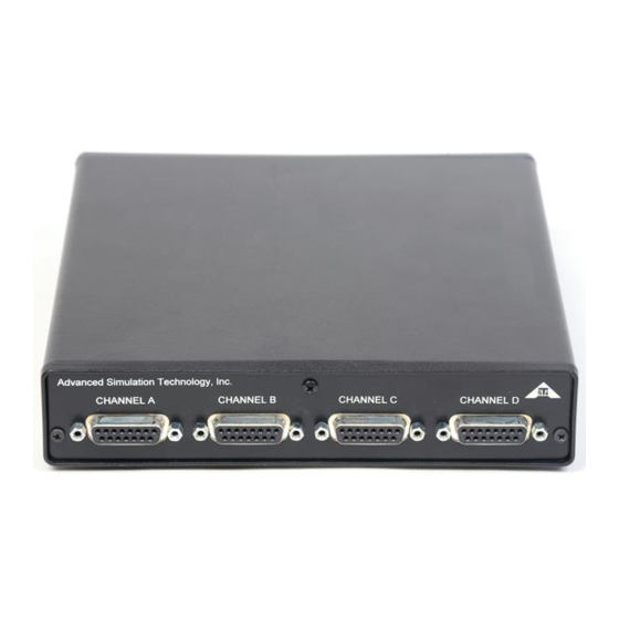
Table 2: Specifications for ACU2 (v2)s without bezels 2.3 Weight A packaged ACU2 (v2) weighs 2 lbs. The power supply included with the ACU2 (v2) weighs 0.5 lbs. 2.4 Front panel The front panel features four DB-15 connectors that are compatible with a variety of audio... -
Page 14: Audio Interface: Db-15 Pinout
Figure 6: Interface connection DB-15 female 2.5 Rear panel Figure 7, "Rear panel of ACU2 (v2) without bezels" below shows the ACU2 (v2) rear panel: Figure 7: Rear panel of ACU2 (v2) without bezels Copyright © 2022 Advanced Simulation Technology inc. -
Page 15: Serial Ports
ACU2 (v2) Technical User Guide (Rev. A, Ver. 0) 2.5.1 Serial ports The ACU2 (v2) has two serial ports that provide a control interface for ASTi handheld ter- minals (HHTs), simulated panels, and live radio control. Figure 8, "RJ-12 pin out: RS-422 mode"... -
Page 16: Status Indicator Lights
ACU2 (v2) Technical User Guide (Rev. A, Ver. 0) 2.5.2 Status indicator lights The ACU2 (v2) LED indicator lights display the ACU2 (v2)'s status: LED Lights Status Location Flashing green Bottom Normal operation. Internal board failure. One red flash + three No LAN link. -
Page 17: Acenet Connection
ACU2 (v2) Technical User Guide (Rev. A, Ver. 0) 2.5.4 ACENet connection The ACU2 (v2)'s ACENet port connects to an ACENet-compatible switch via a Category 5e (CAT5e) cable or better. Device Cable Length ACU2 (v2) 100 meters (328 feet) Server... - Page 18 ACU2 (v2) Technical User Guide (Rev. A, Ver. 0) 2.5.4.2 ACENet indicator lights The ACENet LED indicator lights display the port status: LED Light Status Solid green Network link. Flashing green Network activity. Solid or flashing One ACENet device per network functions as the ACENet master and is iden- amber tified with a flashing amber light.
-
Page 19: Audio Input And Output
-8 dB, +2 dB to +57 dB; default value of 40 dB; software configurable Note: The ACU2 (v2) gain covers a total range of 65 dB. Between +2 dB and +57 dB, the gain can be set in 1 dB steps. A value of -8 dB is available for input signals greater than line level. -
Page 20: Microphone Power
Figure 11: Microphone power diagram Caution: Do not connect a microphone requiring phantom power to an ACU2 (v2) device, as this will damage the microphone. If you are unsure of the difference between microphone power and phantom power, contact the microphone manufacturer or ASTi before connecting equipment. -
Page 21: Input Frequency Response
ACU2 (v2) Technical User Guide (Rev. A, Ver. 0) 3.1.2 Input frequency response Figure 12, "ACU2 (v2) input frequency response" below shows an ACU2 (v2)'s input fre- quency response: Figure 12: ACU2 (v2) input frequency response 3.2 Audio output Table 8, "ACU2 (v2) audio output" below shows an ACU2 (v2)'s audio output:... -
Page 22: Audio Isolation Characteristics
Ch. 1 input to Ch. 2 input Table 9: Audio isolation characteristics 3.2.2 Output frequency response Figure 13, "ACU2 (v2) output frequency response" below shows an ACU2 (v2)'s output fre- quency response: Figure 13: ACU2 (v2) output frequency response Copyright © 2022 Advanced Simulation Technology inc. -
Page 23: Control Input And Output
(PTT) device. The control input can function as a digital input or an analog input. In both cases, the ACU2 (v2) component in the model will be able to read the control input value and use this value as required for the application. -
Page 24: Control Input Used As A Digital Input
The control input can be used as an analog input by inserting a resistance between the control input and control input ground pins. With this configuration the ACU2 (v2) component in the model will map the voltage to an uint8 value that can be used in modeling your application. -
Page 25: Digital Output
ACU2 (v2) Technical User Guide (Rev. A, Ver. 0) 4.2 Digital output The digital output circuitry consists of an opto-isolated, solid-state relay for switching power to external loads. Type Opto-isolated Field-Effect Transistor (FET) Maximum continuous current rating 120 mA Maximum power dissipation... -
Page 26: Typical Headset Connections
ACU2 (v2) Technical User Guide (Rev. A, Ver. 0) 5.0 Typical headset connections The following sections show diagrams for mono and stereo headset connections. 5.1 Mono headset connection Figure 19, "Mono headset connection" below shows a mono headset connection: Figure 19: Mono headset connection 5.2 Stereo headset connection... -
Page 27: Software Configuration
ACU2 (v2) Technical User Guide (Rev. A, Ver. 0) 6.0 Software configuration For software configuration instructions, go to the Remote Management System User Guide. Copyright © 2022 Advanced Simulation Technology inc. -
Page 28: Earth-Ground The Acu2 (V2)
ACU2 (v2) Technical User Guide (Rev. A, Ver. 0) 7.0 Earth-ground the ACU2 (v2) ASTi does not require the ACU2 (v2) to be grounded. However, it was designed to accom- modate customers with strict grounding policies and requirements. To reduce resistance, keep your grounding wire as short as possible. -
Page 29: Update Firmware
ACU2 (v2) Technical User Guide (Rev. A, Ver. 0) 8.0 Update firmware For ACU2 (v2) firmware update instructions for Telestra software, go to the Remote Man- agement System User Guide. Copyright © 2022 Advanced Simulation Technology inc. -
Page 30: Rackmount Acu2 (V2)S
3. Remove the faceplate with the white lettering and the bezel. Save the bezel for when you remove the ACU2 (v2) from the rackmount. 4. Place the ACU2 (v2) into the backside of the rackmount. The rackmount fits in place of the bezel. -
Page 31: Power Daisy Chain
6. Install the jackscrews on each side of the four connectors. Figure 22: ACU2 (v2) rackmount installation Note: The included rackmount kits are compatible with a variety of ASTi audio distribution devices. As a result, you can mount different device types next to each other in the same rack. - Page 32 ACU2 (v2) Technical User Guide (Rev. A, Ver. 0) Figure 23, "Power daisy chain connectors" below shows power daisy chain connectors: Figure 23: Power daisy chain connectors Copyright © 2022 Advanced Simulation Technology inc.
-
Page 33: Bottom Mounting Diagram
ACU2 (v2) Technical User Guide (Rev. A, Ver. 0) 9.2 Bottom mounting diagram Figure 24: ACU2 (v2) bottom mounting diagram Copyright © 2022 Advanced Simulation Technology inc. -
Page 34: Specifications
Temperature and humidity ranges 10.1 Power requirements The ACU2 (v2) is shipped with a standard power supply, which provides power to one ACU2 (v2). The power supply should only be connected to a grounded outlet. To rackmount the ACU2 (v2), you may need to purchase an upgraded power daisy chain. For more information about the power daisy chain, go to Section 9.1, "Power daisy chain"... -
Page 35: Memory Devices
Storage Humidity Range 5% to 95% Table 13: Temperature and humidity ranges 10.4 Reliability The following table shows an ACU2 (v2)'s typical Mean Time Between Failure (MTBF) rate for commercial off-the-shelf (COTS) and military (MIL) systems: Category MTBF Rate COTS... -
Page 36: Appendix A: Warranty Information
RMA number. The shipping label must also include the RMA number. Any items received from customers without RMA numbers or appro- priate contact information will not be tested. After 60 days, ASTi reserves the right to scrap all hardware received in this condition. - Page 37 FedEx, unless otherwise directed. ASTi is responsible for return shipping charges on domestic items under warranty. If ASTi does not receive the equipment 30 days after the RMA was issued, ASTi closes the RMA and designates it as unused.
Need help?
Do you have a question about the ACU2 and is the answer not in the manual?
Questions and answers