Table of Contents
Advertisement
Quick Links
ACU2 Technical User Guide
Document: DOC-HW-ACU2-UG-L-1
Advanced Simulation Technology inc.
500A Huntmar Park Drive, Herndon, Virginia 20170 USA
Revision L, Version 1 (December, 2017)
Advanced Simulation Technology inc.
500A Huntmar Park Drive
Herndon, Virginia 20170 USA
Tel. (703) 471-2104 • Fax. (703) 471-2108
www.asti-usa.com
Advertisement
Table of Contents

Subscribe to Our Youtube Channel
Related Manuals for ASTi ACU2


Summary of Contents for ASTi ACU2
- Page 1 500A Huntmar Park Drive Herndon, Virginia 20170 USA Tel. (703) 471-2104 • Fax. (703) 471-2108 www.asti-usa.com ACU2 Technical User Guide Document: DOC-HW-ACU2-UG-L-1 Advanced Simulation Technology inc. 500A Huntmar Park Drive, Herndon, Virginia 20170 USA Revision L, Version 1 (December, 2017)
- Page 3 Product Name: ACU2 ACU2 Technical User Guide © Copyright ASTi 2017 Restricted Rights: Use, duplication, or disclosure by the Government is subject to restrictions as set forth in subparagraph (c)(1)(ii) of the Rights in Technical Data and Computer Software clause at DFARS 252.227-7013.
-
Page 4: Revision History
Revision history Date Revision Version Comments 10/4/2017 Convert original content to XML and edit for grammar and accuracy. 12/8/2017 Edit "Analog In" figure in "Control input used as analog input."... -
Page 5: Table Of Contents
Contents 1.0 Introduction 2.0 Physical description 2.1 ACU2 with bezels 2.2 ACU2 without bezels 2.3 Weight 2.4 Front panel 2.4.1 Audio interface: DB-15 pinout 2.5 Rear panel 2.5.1 Serial ports 2.5.2 Status indicator lights 2.5.3 DIP switch positions 2.5.4 ACENet connection 3.0 Audio input and audio output... - Page 6 5.1 Mono headset connection 5.2 Stereo headset connection 6.0 Software configuration 7.0 Earth ground 8.0 Firmware updates 9.0 Rackmount ACU2s 9.1 Power daisy chain 10.0 Specifications 10.1 Power requirements 10.2 Memory devices 10.3 Temperature and humidity ranges 10.4 Reliability 11.0 Warranty information 11.1 Repairs and returns...
-
Page 8: Introduction
ACU2 Technical User Guide (Rev. L, Ver. 1) 1.0 Introduction The ACU2 is a compact, 48 kHz digital and audio distribution module that connects remotely located operator stations and live radios to the ACENet network. The ACU2 is compatible with the Telestra and Voisus platforms. - Page 9 ACU2 Technical User Guide (Rev. L, Ver. 1) The following figure shows an example of an ACU2 hardware configuration: Figure 1: ACU2 hardware configuration Copyright © 2017 Advanced Simulation Technology inc.
-
Page 10: Physical Description
2.1 ACU2 with bezels The ACU2 has two bezels, encompassing the front and rear panels. This ACU2 is Conformitè Europèene (CE)/Restriction of Hazardous Substances (RoHS) certified. Removing the bezels voids the CE certification. The following figure shows the ACU2 front bezel:... -
Page 11: Acu2 Without Bezels
ACU2 Technical User Guide (Rev. L, Ver. 1) The following figure shows ACU2 bezel side dimensions: Figure 4: ACU2 bezel side dimensions 2.2 ACU2 without bezels Older versions of the ACU2 do not have bezels. The following table shows the specification for ACU2s without bezels: Specification Description Length 7.5"... -
Page 12: Front Panel
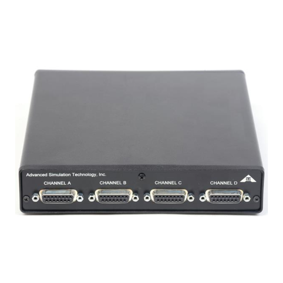
The front panel features four DB-15 connectors that are compatible with a variety of audio and press-to-talk (PTT) devices. 2.4.1 Audio interface: DB-15 pinout The following figure shows a DB-15 pinout for the ACU2 audio interface: Figure 6: Interface connection DB-15 female Copyright © 2017 Advanced Simulation Technology inc. -
Page 13: Rear Panel
Table 2: Rear panel callouts 2.5.1 Serial ports The ACU2 has two serial ports that provide a control interface for ASTi hand-held terminals (HHTs), simulated panels, and live radio control. The following figure shows an RJ-12 female serial connection in RS-422 mode: Figure 8: RJ-12 pin out: RS-422 mode Copyright ©... -
Page 14: Status Indicator Lights
The ACU2 LED indicator lights display ACU2 status: LED Lights Status Location Flashing green Bottom Normal operation. Solid green Bottom The ACU2 started up properly, but the ACENet is disconnected. Internal board failure. Table 3: Status indicator lights Copyright © 2017 Advanced Simulation Technology inc. -
Page 15: Dip Switch Positions
Important: Customer-made cables are the primary reason for product failure. ASTi recom- mends high-quality, manufactured CAT5e cables. Alternatively, the ACU2 can connect directly to the Telestra or Voisus server using a crossover cable. The ACU2 does not support daisy chaining to additional units or internal switching across networks. - Page 16 ACU2 Technical User Guide (Rev. L, Ver. 1) 2.5.4.1 RJ-45 ACENet connection pinout The following figure shows an RJ-45 ACENet connection pinout: Figure 10: RJ-45 ACENet connection pin out 2.5.4.2 ACENet indicator lights The ACENet LED indicator lights display the port status:...
-
Page 17: Audio Input And Audio Output
-8 dB, +2 dB to +57 dB, software configurable Note: The ACU2 gain covers a total range of 65 dB. Between +2 dB and +57 dB, the gain can be set in 1 dB steps. A value of -8 dB is available for input signals greater than line level. -
Page 18: Microphone Power
Figure 11: Microphone power diagram Caution: Do not connect a microphone requiring phantom power to an ACU2 device, as this will damage the microphone. If you are unsure of the difference between microphone power and phantom power, contact the microphone manufacturer or ASTi before connecting equip- ment. -
Page 19: Input Frequency Response
ACU2 Technical User Guide (Rev. L, Ver. 1) 3.1.2 Input frequency response The following figure shows an ACU2's input frequency response: Figure 12: ACU2 input frequency response 3.2 Audio output The following table shows an ACU2's audio output: Output Impedance... -
Page 20: Audio Isolation Characteristics
Ch. 1 output to Ch. 2 input Ch. 1 input to Ch. 2 input Table 8: Audio isolation characteristics 3.2.2 Output frequency response The following figure shows an ACU2's output frequency response: Figure 14: ACU2 output frequency response Copyright © 2017 Advanced Simulation Technology inc. -
Page 21: Control Input And Output
(PTT) device. The control input can function as a digital input or an analog input. In both cases, the ACU2 component in the model will be able to read the control input value and use this value as required for the application. -
Page 22: Control Input Used As A Digital Input
The uint8 number read in the ACU2 software component will vary by a given percentage based on the tolerances of all of the com- ponents involved. -
Page 23: Digital Output
ACU2 Technical User Guide (Rev. L, Ver. 1) 4.2 Digital output The digital output circuitry consists of an opto-isolated, solid-state relay for switching power to external loads. Type Opto-isolated Field-Effect Transistor (FET) Maximum continuous current rating 120 mA Maximum power dissipation... -
Page 24: Typical Headset Connections
ACU2 Technical User Guide (Rev. L, Ver. 1) 5.0 Typical headset connections The following sections show diagrams for mono and stereo headset connections. 5.1 Mono headset connection The following figure shows a mono headset connection: Figure 20: Mono headset connection 5.2 Stereo headset connection... -
Page 25: Software Configuration
ACU2 Technical User Guide (Rev. L, Ver. 1) 6.0 Software configuration For software configuration instructions, reference the following: Name Description Telestra See the Telestra Remote Management System User Guide on the Telestra Support page. Voisus See “Voisus Hardware Clients” in the Voisus Client User Guide on the Voisus Support page. -
Page 26: Earth Ground
ACU2 Technical User Guide (Rev. L, Ver. 1) 7.0 Earth ground ASTi does not require the ACU2 to be grounded. However, it was designed to accommodate customers with strict grounding policies and requirements. To reduce resistance, keep your grounding wire as short as possible. This practice effectively dissipates an unwanted electrical charge. -
Page 27: Firmware Updates
1. In the Voisus web interface, from the top-right navigation bar, click Manage, and then click Hardware Devices. 2. Click the ACU2 tab. A message displays if any connected ACU2s need a firmware update. 3. To complete the procedure, follow the on-screen instructions. -
Page 28: Rackmount Acu2S
3. Remove the faceplate with the white lettering and the bezel. Save the bezel for when you remove the ACU2 from the rackmount. 4. Place the ACU2 into the backside of the rackmount. The rackmount fits in place of the bezel. -
Page 29: Power Daisy Chain
ACU2 Technical User Guide (Rev. L, Ver. 1) 9.1 Power daisy chain The power daisy chain connection enables operation of two rackmounted ACU2 units from a single-power supply. Daisy chaining ACU2 power requires an upgraded power supply (model number TR7 A15 from CINCON Electronic Co. LTD). Contact ASTi for details. The daisy chain cable (P-760K-S765K-16-A) is included with the upgraded power supply. -
Page 30: Specifications
10.1 Power requirements The ACU2 is shipped with a standard power supply, which provides power to one ACU2. The power supply should only be connected to a grounded outlet. To rackmount the ACU2s, you may need to purchase an upgraded power daisy chain. For more information about the power daisy chain, see Section 9.1, "Power daisy chain"... -
Page 31: Temperature And Humidity Ranges
30°C (86°F) per hour Storage Humidity Range 5% to 95% Table 14: Temperature and humidity ranges 10.4 Reliability The following table shows an ACU2's typical Mean Time Between Failure (MTBF) rate for commercial off-the-shelf (COTS) and military (MIL) systems: Category MTBF Rate COTS 108,100.75 hours... -
Page 32: Warranty Information
RMA numbers or appropriate contact information will not be tested. After 60 days, ASTi reserves the right to scrap all hardware received in this condition. 2. When packaging the equipment in question, make sure it is well-protected. Failure to prop- erly package the equipment during shipping could void the warranty. - Page 33 FedEx, unless otherwise directed. ASTi is responsible for return shipping charges on domestic items under warranty. If ASTi does not receive the equipment 30 days after the RMA was issued, ASTi closes the RMA and designates it as unused.
Need help?
Do you have a question about the ACU2 and is the answer not in the manual?
Questions and answers