Table of Contents
Advertisement
Quick Links
STENCILING & MARKING
SYSTEMS
OWNER'S MANUAL
NON-POROUS
LARGE CAPACITY HAND PRINTERS
ALL MODELS
INSTALLATION - OPERATION - MAINTENANCE
UNIVERSAL STENCILING & MARKING SYSTEMS, INC.
P.O. BOX 871 - ST. PETERSBURG, FLORIDA 33731 USA
PH: (727) 894-3027 FAX: (727) 821-7944
E-Mail: sales@universal-marking.com Website: www.universal-marking.com
HPLNP-22115
1
Advertisement
Table of Contents

Subscribe to Our Youtube Channel
Related Manuals for Universal HPL-100NI-NP


Summary of Contents for Universal HPL-100NI-NP
- Page 1 OWNER’S MANUAL NON-POROUS LARGE CAPACITY HAND PRINTERS ALL MODELS INSTALLATION - OPERATION - MAINTENANCE UNIVERSAL STENCILING & MARKING SYSTEMS, INC. P.O. BOX 871 - ST. PETERSBURG, FLORIDA 33731 USA PH: (727) 894-3027 FAX: (727) 821-7944 E-Mail: sales@universal-marking.com Website: www.universal-marking.com HPLNP-22115...
-
Page 2: Table Of Contents
IMPORTANT NOTE UNIVERSAL products are manufactured to exacting standards and every available step has been taken to assure your complete satisfaction. It is most important, for best results, that you read and carefully follow the instructions contained in this manual. Failure to do so may result in unsatisfactory performance, damage to the equipment and personal injury. -
Page 3: Preface
PREFACE The Universal HPL Non-Porous Hand Printers were designed to print lot numbers, date codes, and text information on metal, plastics & other non-porous surfaces. Universal Large Capacity Hand Printers are precision engineered to give years of reliable service under the most demanding conditions. -
Page 4: Specifications
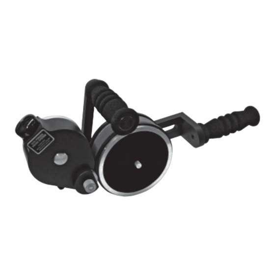
SPECIFICATIONS HPL-NP PRINTER SPECIFICATIONS HPL-100-NP SERIES Model Shown: HPL-100NI-NP 17.19” 436.6 MM 16.41” 416.8 MM 3.68” 6.71” 93.5 MM 170.4 MM 1.04” 26.4 MM 5.74” 145.8 MM 8.45” 214.6 MM NET WEIGHT: 7.03 LBS. (3.19 KG) MAXIMUM DIE SIZE - US STANDARD: 1”... -
Page 5: Hpl-200-Np Series
SPECIFICATIONS HPL-NP PRINTER SPECIFICATIONS HPL-200-NP SERIES Model Shown: HPL-200NI-NP 17.19” 436.6 MM 16.41” 416.8 MM 6.71” 5.58” 170.4 MM 141.7 MM 1.95” 49.5 MM 5.74” 145.8 MM 8.45” 214.6 MM NET WEIGHT: 8.23 LBS. (3.73 KG.) MAXIMUM DIE SIZE - US STANDARD: 1-15/16”... -
Page 6: Indexing & Non-Indexing Models
Universal’s Non-Porous Inking System is compatible with a wide range of alcohol base marking inks. Although we offer a variety of inks for specific applications, you are not restricted to using only Universal brand inks. When selecting inks from other manufacturers however, it is your responsibility to make sure the inks are compatible with the coder. -
Page 7: Printing Dies
FIGURE 3 METRIC RIBtype® PRINTING DIES Universal also offers Metric RIBtype® die systems for use in countries where metric character sizes are the standard. The Metric dies are thicker and the rib spacing differs slightly from the standard printing dies therefore the two versions are not compatible. -
Page 8: Ink Rolls
SPECIFICATIONS INK ROLLS Universal offers two ink roll options for the HPL Non-Porous Hand Printers. Each has a unique characteristic suitable for a specific printing application. The printers are designed to accommodate both types of ink rolls without modification. A detailed review of your printing requirements will determine the best choice of ink rolls for your particular application. -
Page 9: Quick Start
PRE-INKING XF NEOPRENE INK ROLLS Universal HPL Non-Porous Hand Printers are shipped from the factory fully assembled and, unless otherwise specified, includes a dry XF Neoprene Ink Roll. The initial inking of any dry roll is critical to the preformance of the Printer. -
Page 10: Installing The Pre-Inked Roll
QUICK START Warning: Non-Porous inks contain flammable solvents. Do not smoke or handle these rolls in the presence of sparks or open flames. Inks will also stain clothing, furniture, carpeting and your hands. Rubber gloves should be worn during the following procedures. The ink roll you install on the coder must be properly pre-inked. - Page 11 QUICK START 4 - Remove the Knurled Drive Wheel “E”. The Knurled Drive Wheel rests on top of the Transfer Roll “G”. The Transfer Roll has 3 stainless, protruding drive pins which fit through 3 mating holes in the Knurled Drive Wheel “E”.
- Page 12 QUICK START 8 - Install the ink roll on the Ink Roll Axle by aligning the end of the rod or pencil with the end of the axle and pushing the roll onto the axle. When this step is complete, remove the rubber gloves to prevent ink contamination with the external parts of the coder.
-
Page 13: Installing The Printing Dies
QUICK START 12 - Replace the Cover Retaining Knob “C” and lightly tighten. Do not over tighten this knob or you may bend the top of the Drive Wheel Cover “B” and cause it to bind against the Knurled Drive Wheel. The Cover Retaining Knob should be just tight enough to keep the Inking System Assembly together and prevent the Drive Wheel Cover from rotating out of... -
Page 14: Adjusting The Ink Roll / Die Face Contact Pressure
QUICK START ADJUSTING THE TRANSFER ROLL / DIE FACE CONTACT PRESSURE The pressure the transfer roll exerts on the face of the printing dies should be just enough to rotate the transfer roll and completely ink the face of the dies as they pass during printing. Excessive contact pressure will cause smudging of the impression, and restriction of the print drum rotation. -
Page 15: Printing Die Positioning For Indexing Applications
QUICK START PRINTING DIE POSITIONING FOR INDEXING APPLICATIONS Non-indexing models of the HPL Non-Porous Hand Printers do not offer print registration capabilities, therefore mounting the printing dies at a specific location on the print drum is not important. On indexing machines, the position of the die on the print drum will determine the location of the print on the carton. -
Page 16: Maintenance
MAINTENANCE CLEANING THE TRANSFER ROLL The surface of the transfer roll is made from DuPont Delrin material and the O.D. of the roll is finely engraved which enables it to hold a uniform film of ink. This surface material is very fragile and under no circumstances should you attempt to clean it with anything abrasive. -
Page 17: Cleaning The Printing Dies
MAINTENANCE CLEANING THE PRINTING DIES All inks which are formulated for printing on non-porous surfaces contain a resin binder which bonds the dye or pigment in the ink to the surface of the material being printed. As the ink begins to dry, this binder becomes “tacky”... -
Page 18: Print Drum Index Mechanism Maintenance
PRINT DRUM INDEX MECHANISM MAINTENANCE PRINT DRUM INDEX MECHANISM DISASSEMBLY / ASSEMBLY 1- Using a 5/64” hex wrench, loosen the Nylon Tip Set Screw located in the top rim of the Print Drum and remove the dust cover. FIGURE 31 2- To relieve the spring tension on the index mechanism, rotate the Print Drum approximately 3/4 turn. -
Page 19: Replacing Print Drum Index Springs
PRINT DRUM INDEX MECHANISM MAINTENANCE 5- Using a 1/8" hex wrench, loosen the Brass Tipped Set Screw located in the side of the Index Ring. This screw must be turned counterclockwise at least two full revolutions. FIGURE 39 6- Remove the Index Ring from the axle by turing it in a Counter-Clockwise direction. -
Page 20: Removing & Replacing Index Block "B
PRINT DRUM INDEX MECHANISM MAINTENANCE REMOVING AND REPLACING INDEX BLOCK “B” If the Indexing Assembly Block “B” is removed during disassembly it must be realigned using the following procedure. 1- To remove Index Block “B” from the Print Drum, roll down the Drum Cover directly behind the Index Block to expose the Index Assembly Mounting Screw. - Page 21 PRINT DRUM INDEX MECHANISM MAINTENANCE 4- If the Brass Tip Set Screw is not pointing in the direction shown in Figure 47, rotate the Index Ring in a Counter- SET SCREW Clockwise Direction until it points in the direction shown. FIGURE 47 5- Tighten the Brass tip Set Screw securely to prevent the Index Ring from rotating when under spring tension.
-
Page 22: Parts Diagrams And Parts Lists
HPL-NP PRINTER ASSEMBLY... - Page 23 HPL-NP PRINTER KEY NO. QTY. REQUIRED PART NUMBER DESCRIPTION MC-02 SCREW, 1/4-20 X 5/8 LG SOC HD CAP HPL-001 SIDE FRAME 3/8” BRASS FLAT WASHER HP-04 MRM-CL20 KNOB HPL-HA HANDLE ASSEMBLY USMR-032 SCREW, 5/16-18 X 1.250 CPSS SCREW, 1/4-20 X 0.5 SHCS NP-23 HPL-020 INKING SYSTEM MOUNTING PAD...
- Page 24 HPL-NP PRINT DRUM PART NUMBER DESCRIPTION KEY NO. QTY. REQD. CO-02S BEARER RING CLP-BL1 CLP/HPL-100-RIBtype® DRUM COVER CLP/HPL-200-RIBtype® DRUM COVER CLP-BL2 CLP/HPL-100-RIBtype® DRUM COVER - METRIC CLP-BL1T CLP/HPL-200-RIBtype® DRUM COVER - METRIC CLP-BL2T PRINT DRUMS ONLY AVAILABLE IN COMPLETE PRINT DRUM ASSEMBLIES SEE PAGES 22 &...
- Page 25 HPL-NP INDEXING ASSEMBLY PART NUMBER DESCRIPTION KEY NO. QTY. REQUIRED SNAP RING CF-28 CLP-IA INDEX ASSEMBLY BLOCK “A” CF-27 INDEX ASSEMBLY MOUNTING SCREW INDEX ASSEMBLY BLOCK “B” CLP-IB CS-07 DRUM INDEX SPRING CLP-IC INDEX ASSEMBLY BLOCK “C” CF-04 SET SCREW, 1/4-20, BTSS INDEX RING ASSEMBLY CLP-IR2 INDEX PLUNGER ASSEMBLY...
- Page 26 HPL NON-POROUS INKING SYSTEM...
- Page 27 HPL NON-POROUS INKING SYSTEM PART NUMBER QTY. REQD. DESCRIPTION KEY NO. SET SCREW, 8-32 X 3/16” CPS HP-06 NP-19 ECCENTRIC KNURLED KNOB NP-04-RT MC INKING SYSTEM BASEPLATE - RIGHT HAND TOP MOUNT ASSEMBLY DELRIN WASHER HP-42 NP-20M INK ROLL ECCENTRIC NP-07 1”...
Need help?
Do you have a question about the HPL-100NI-NP and is the answer not in the manual?
Questions and answers