Table of Contents
Advertisement
Quick Links
STENCILING & MARKING
SYSTEMS
OWNER'S MANUAL
POROUS
HAND PRINTER
ALL MODELS
OPERATION - MAINTENANCE
UNIVERSAL STENCILING & MARKING SYSTEMS, INC.
P.O. BOX 871 - ST. PETERSBURG, FLORIDA 33731 USA
PH: (727) 894-3027 FAX: (727) 821-7944
E-Mail: sales@universal-marking.com Website: www.universal-marking.com
Page 1 of 27
PHP-18122
Advertisement
Table of Contents

Subscribe to Our Youtube Channel
Related Manuals for Universal HP-100NI


Summary of Contents for Universal HP-100NI
- Page 1 OWNER’S MANUAL POROUS HAND PRINTER ALL MODELS OPERATION - MAINTENANCE UNIVERSAL STENCILING & MARKING SYSTEMS, INC. P.O. BOX 871 - ST. PETERSBURG, FLORIDA 33731 USA PH: (727) 894-3027 FAX: (727) 821-7944 E-Mail: sales@universal-marking.com Website: www.universal-marking.com Page 1 of 27 PHP-18122...
-
Page 2: Table Of Contents
PARTS DIAGRAMS & PARTS LISTS - LIMITED WARRANTY - UNIVERSAL Hand Printers are guaranteed to be free from defects in materials and workmanship for a period of 90 days from the date of purchase. Components found to be defective during this time will be repaired free of charge if returned to the factory. Damage resulting from use of improper inks, improper installation, or operation is not covered under the scope of this warranty. - Page 3 SPECIFICATIONS HP-100NI HAND PRINTER NET WEIGHT: 1LB - 6 OZ. / 0.614 KG. MAXIMUM DIE SIZE - US STANDARD: 2” (15 RIBS) X 5-9/16” LONG MAXIMUM DIE SIZE - METRIC CODERS ONLY: 50.8 MM (14 RIBS) X 141.3 MM LONG PRINT DRUM CIRCUMFERENCE: 6.5”...
- Page 4 SPECIFICATIONS HP-200 & HP-200NI HAND PRINTER HP-200: NET WEIGHT: 1 LB. - 12 OZ. / 0.781 KG. MAXIMUM DIE SIZE - US STANDARD: 2” (15 RIBS) X 8-3/8” LONG MAXIMUM DIE SIZE - METRIC CODERS ONLY: 50.8 MM (14 RIBS) X 212.7 MM LONG PRINT DRUM CIRCUMFERENCE: 9.1”...
-
Page 5: Printing Die's
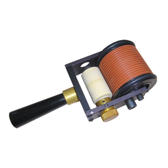
SPECIFICATIONS The Universal HP-100NI, HP-200NI and HP-200 hand printers are designed for the hand application of printed data on cartons, bags and other flat, porous surface materials The HP-100NI and HP-200NI machines are non-indexing or continuous roll de- signs. The HP-200 machine is an indexing or spot printing design which allows for accurate print registration and eliminates duplication of data. -
Page 6: Optional Type Blocking Kit
Microcell rolls should be inked with Universal No. 1150 porous coder ink only. It is extremely important to fol- low the inking instructions or roll performance will be adversely affected. -
Page 7: Quick Start
QUICK START PRE-INKING THE MICROCELL INK ROLL Universal Hand Printers are shipped from the factory fully assembled and, unless otherwise specified, include a dry Microcell Ink Roll. The Ink Roll must be manu- ally pre-inked prior to use. The initial inking of a dry roll is a critical process. The following instructions will guide you through the inking and installation process and have your coder ready to use in a few minutes. - Page 8 QUICK START 5 - Rotate the Ink Roll Eccentric Knob until the Ink Roll Axle is at its farthest position away from the print drum. In this position, the ink roll will not contact the print drum during installation. FIGURE 7 6 - Remove the Ink Roller Axle from the coder.
-
Page 9: Re-Inking The Microcell Ink Roll
QUICK START 9 - Adjust the Ink Roller Eccentric Knob to a position where the ink roll just contacts the die faces when the print drum is rotated. Ink should only be applied to the die face, not the sides or backing of the die. Excessive contact pres- sure will result in an excessively wet and smudged impression. -
Page 10: Maintenance
MAINTENANCE REPLACING THE DRUM COVERING Replacing the Drum Covering requires removal of the print drum. The following steps explain the process. For Indexing Coders, see Page 12 under Index Spring Replacement for Print Drum removal instructions. 1 - Lay the coder on it’s side as shown and using a 5/64”... - Page 11 MAINTENANCE 5 - Remove one of the Rubber Friction Bearer Rings. It does not matter which one is removed. FIGURE 17 6 - Remove the old Print Drum Cover by grip- ping one edge with your fingertips and roll- ing the cover towards the end of the Print Drum where the friction bearer was re- moved.
-
Page 12: Replacing The Print Drum Index Spring On The Hp-200 Indexing Coder
MAINTENANCE REPLACING THE PRINT DRUM INDEX SPRING ON THE HP-200 INDEXING CODER Replacing the Index Spring requires removal of the print drum. Please follow these same disassembly steps for replacing the Drum Cover. 1 -Remove the Index Stop Pin and Washer us- ing a 5/16”... - Page 13 MAINTENANCE 5 -Lift the Side Frame off the coder. A slight wiggling action may help disengage the Side Frame from the Print Drum Axle. Figure 26 6 -Lift the Print Drum off the Axle. Figure 27 7 -Remove the Index Cam. The Index Cam on this unit enables the Print Drum to rotate 365 degrees before hitting the Stop Pin.
- Page 14 MAINTENANCE 10 -Remove the small white bushing from the opposite end of the Print Drum. The bushing will exit through the bottom of the Print Drum as shown. Figure 31 11 -Install the new Index Spring. Insert your index finger through the large hole in the print drum and use it to guide the spring as it is in- serted through the small hole.
- Page 15 MAINTENANCE 15 -Install the Print Drum and engage the oppo- site end of the spring with the slot in the Print Drum Axle. Set the Print Drum on the bench with the small plastic bushing up. Carefully guide the end of the axle about half way into the hole and stop.
-
Page 16: Adjusting The Tension Of The Index Spring
MAINTENANCE 20 -Install the Spring Tension Adjuster in the slot in the end of the Print Drum Axle. The tension adjuster should be pushed fully into the axle slot. Figure 41 21 -Install the Index Stop Pin & Washer. Rotate the Print Drum in a clockwise direction until the arced slot in the Index Cam is directly below the hole for the Stop Pin. - Page 17 MAINTENANCE 2 -Insert a 3/16” hex wrench in the socket head of the Spring Tension Adjuster. While hold- ing the wrench firmly in position so it does not turn, use a 9/64” hex wrench to loosen the other Axle Retaining Screw. Once the second Axle Retaining Screw is loose, the Index Spring will try to relax and rotate the Tension Figure 45...
-
Page 18: Assembly Of The Ink Roller Eccentric
MAINTENANCE ASSEMBLY OF THE INK ROLLER ECCENTRIC Proper installation of the Ink Roller Eccentric Assembly is critical to the perfor- mance of the coder and uniform inking of the printing dies. It is easiest to as- semble these parts properly with the Side Frame removed from the coder. 1 -Loosen the nylon tipped Tension Adjusting Set Screw. - Page 19 MAINTENANCE 5 -Install the Locking Collar. Set the assembly on the bench with the knurled end of the Eccentric Adjusting Knob down. Using your fingertips, press down hard on the Locking Collar. It is important that the Locking Collar is tight against the Side Frame for this assembly to work properly.
-
Page 20: Parts Diagrams & Parts Lists
POROUS HAND PRINTER HP-100NI & HP-200NI SERIES Page 20 of 26... - Page 21 SCREW, 8-32 X 1/2” BHC HP-11 ECCENTRIC ADJUSTING KNOB HP-42 DELRIN WASHER CF-05 SET SCREW, 8-32 X 3/16” S.S. NTS HP-100NI SIDE FRAME FOR TENSION SCREW HP-08 HP-200NI SIDE FRAME FOR TENSION SCREW HP-28 SET SCREW, 8-32 X 1/8” CPS HP-13 HP-12...
- Page 22 MC-21T HP-200NI RIBtype® RING - METRIC HP-100NI CENTER TUBE/END CAP ASSY. HP-101 HP-200NI CENTER TUBE/END CAP ASSY. HP-201 HP-100NI CENTER TUBE/END CAP ASSY - METRIC HP-101-T HP-200NI CENTER TUBE/END CAP ASSY - METRIC HP-201-T HP-02 PRINT DRUM BEARING HP-100NI / HP-100NI-T FRICTION BEARER RING...
- Page 23 PARTS LISTS FOR INDEXING HAND PRINTER ON THE FOLLOWING PAGES Page 23 of 26...
- Page 24 POROUS HAND PRINTER HP-200 SERIES Page 24 of 26...
- Page 25 POROUS HAND PRINTER HP-200 SERIES PART QTY. DESCRIPTION NUMBER REQ. BLACK HANDLE HP-18 HANDLE BUSHING HP-17 HP-13 SET SCREW, 8-32 X 1/8” CPS LOCKING COLLAR HP-12 SCREW, 8-32 X 1/2” BHC HP-10 DELRIN WASHER HP-42 ECCENTRIC ADJUSTING KNOB HP-11 STOP PIN HP-36 STOP PIN WASHER HP-43...
- Page 26 POROUS HAND PRINTER PRINT DRUM HP-200 SERIES PART QTY. DESCRIPTION NUMBER REQ. MC-21 HP-200 RIBtype® RING MC-21T HP-200 RIBtype® RING - METRIC HP-31 END CAP “A” BUSHING HP-202 HP-200 CENTER TUBE/END CAP A& B BUSHING ASSEMBLY HP-202-T HP-200T CENTER TUBE/END CAP A& B BUSHING ASSY. METRIC HP-200 BEARER RING MC-01 HP-32...
Need help?
Do you have a question about the HP-100NI and is the answer not in the manual?
Questions and answers