Table of Contents
Advertisement
Quick Links
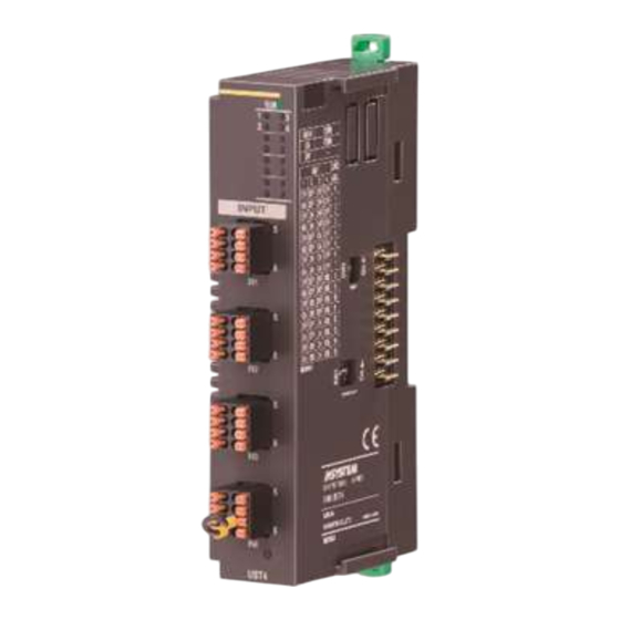
INSTRUCTION MANUAL
UNIVERSAL INPUT MODULE
(4 points, isolated, tension clamp terminal block)
BEFORE USE ....
Thank you for choosing M-System. Before use, please check
contents of the package you received as outlined below.
If you have any problems or questions with the product,
please contact M-System's Sales Office or representatives.
■ PACKAGE INCLUDES:
Universal input module ......................................................(1)
CJC sensor ...........................................................................(4)
■ MODEL NO.
Confirm Model No. marking on the product to be exactly
what you ordered.
■ INSTRUCTION MANUAL
This manual describes necessary points of caution when
you use this product, including installation, connection and
basic maintenance procedures.
POINTS OF CAUTION
■ CONFORMITY WITH EU DIRECTIVES
• The equipment must be mounted inside a panel.
• The actual installation environments such as panel con-
figurations, connected devices, connected wires, may af-
fect the protection level of this unit when it is integrated
in a panel system. The user may have to review the CE
requirements in regard to the whole system and employ
additional protective measures to ensure the CE conform-
ity.
■ GENERAL PRECAUTIONS
• Before you remove or mount the unit, turn off the power
supply and output signal for safety.
• DO NOT set the switches while the power is supplied.
The switches are used only for maintenance without the
power.
■ ENVIRONMENT
• Indoor use.
• When heavy dust or metal particles are present in the
air, install the unit inside proper housing with sufficient
ventilation.
• Do not install the unit where it is subjected to continuous
vibration. Do not subject the unit to physical impact.
• Environmental temperature must be within -10 to +55°C
(14 to 131°F) with relative humidity within 30 to 90% RH
in order to ensure adequate life span and operation.
■ WIRING
• Do not install cables close to noise sources (relay drive
cable, high frequency line, etc.).
• Do not bind these cables together with those in which
noises are present. Do not install them in the same duct.
5-2-55, Minamitsumori, Nishinari-ku, Osaka 557-0063 JAPAN
Phone: +81(6)6659-8201 Fax: +81(6)6659-8510 E-mail: info@m-system.co.jp
MODEL
■ POWER UP
• Turn the power on at the same time as the power/network
module or turn the R80PS1 on before the power/network
module turned on. If the R80PS1 is not turned on within
3 seconds after the power/network module is turned on,
I/O modules are not correctly recognized.
R80UST4
EM-7028 P. 1 / 9
Advertisement
Table of Contents

Related Manuals for M-system R80UST4


Summary of Contents for M-system R80UST4
- Page 1 ■ POWER UP • Turn the power on at the same time as the power/network Thank you for choosing M-System. Before use, please check module or turn the R80PS1 on before the power/network contents of the package you received as outlined below.
-
Page 2: Installation
More I/O modules can be added in the same manner. When removing the cover, pull it out while squeezing the hooks inward. EM-7028 P. 2 / 9 5-2-55, Minamitsumori, Nishinari-ku, Osaka 557-0063 JAPAN Phone: +81(6)6659-8201 Fax: +81(6)6659-8510 E-mail: info@m-system.co.jp... - Page 3 2) I/O modules cannot hold tightly on the DIN rail by themselves without power/network module. Secure them to the position if necessary by using DIN rail end plates. EM-7028 P. 3 / 9 5-2-55, Minamitsumori, Nishinari-ku, Osaka 557-0063 JAPAN Phone: +81(6)6659-8201 Fax: +81(6)6659-8510 E-mail: info@m-system.co.jp...
-
Page 4: Component Identification
(≤ -15%, ≥ +115%, becomes less than the lower limit or exceeds the upper limit of usable range). Input circuit abnormality (AD converter response failure) EM-7028 P. 4 / 9 5-2-55, Minamitsumori, Nishinari-ku, Osaka 557-0063 JAPAN Phone: +81(6)6659-8201 Fax: +81(6)6659-8510 E-mail: info@m-system.co.jp... - Page 5 Input S – – – RTD-B RTD-B Input L Common Common Common Thermocouple- RTD-A RTD-A Input H – – – – – – EM-7028 P. 5 / 9 5-2-55, Minamitsumori, Nishinari-ku, Osaka 557-0063 JAPAN Phone: +81(6)6659-8201 Fax: +81(6)6659-8510 E-mail: info@m-system.co.jp...
-
Page 6: Setting Range
*1. For details, refer to the users manual of R80CFG ■ CHANNEL BATCH SETTING ITEM SETTING RANGE DEFAULT VALUE Version no. – – Simulate input Normal input Normal input Simulated data EM-7028 P. 6 / 9 5-2-55, Minamitsumori, Nishinari-ku, Osaka 557-0063 JAPAN Phone: +81(6)6659-8201 Fax: +81(6)6659-8510 E-mail: info@m-system.co.jp... -
Page 7: Terminal Connections
For thermocouple input, attach the CJC sensor together with input wining to the input screw terminals. ■ EXTERNAL DIMENSIONS unit : mm (inch) 24 [.94] (3 [.12]) 67 [2.64] (4 [.16]) 55 [2.17] DIN rail (35mm wide) EM-7028 P. 7 / 9 5-2-55, Minamitsumori, Nishinari-ku, Osaka 557-0063 JAPAN Phone: +81(6)6659-8201 Fax: +81(6)6659-8510 E-mail: info@m-system.co.jp... - Page 8 R80UST4 ■ CONNECTION DIAGRAM INTERNAL BUS INTERNAL POWER Universal input 1 Universal input 2 Universal input 3 Universal input 4 EM-7028 P. 8 / 9 5-2-55, Minamitsumori, Nishinari-ku, Osaka 557-0063 JAPAN Phone: +81(6)6659-8201 Fax: +81(6)6659-8510 E-mail: info@m-system.co.jp...
-
Page 9: Wiring Instructions
Applicable wire size: 0.14 − 0.5 mm Stripped length: 7 mm Recommended solderless terminal • AI0,14-6GY0.14mm2(Phoenix Contact) • AI0,25-6YE0.25mm2(Phoenix Contact) • A0,34-70.34mm2(Phoenix Contact) EM-7028 P. 9 / 9 5-2-55, Minamitsumori, Nishinari-ku, Osaka 557-0063 JAPAN Phone: +81(6)6659-8201 Fax: +81(6)6659-8510 E-mail: info@m-system.co.jp...
Need help?
Do you have a question about the R80UST4 and is the answer not in the manual?
Questions and answers