Table of Contents
Advertisement
Quick Links
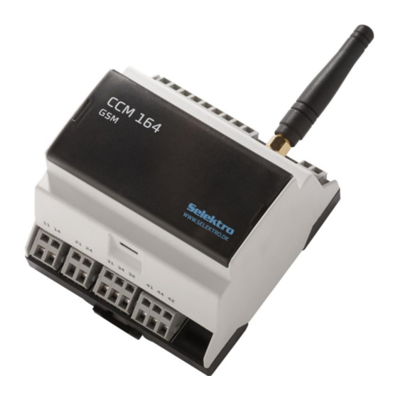
CCM 164 is a control and monitoring module with analog and digital inputs and relay outputs. All inputs and
outputs can be monitored and controlled via SMS (Short Message Service) or via a smartphone app. The
network is defined by the service provider's SIM card.
o An analog 4-20 mA input.
o Six digital (12-24 VDC) or analog (0-10 V) inputs.
o Four relay outputs - 2 power relays and 2 switching relays.
o Two power supply versions, 240Vac and 24VDC
The User Manual can be retrieved from
This manual complies from firmware version 2.1.x.
This manual complies from hardware version 5 and forward.
Selektro A/S, Erhvervsvej 29-35, DK-9632 Møldrup, Denmark
CCM 164 – User Manual – GB / US
CCM 164
Communication and Control Module
www.selektro.dk/ccm
Copyright Selektro A/S 2022
under Manuals.
0881-1344005 V09
Advertisement
Table of Contents

Related Manuals for Selektro CCM 164

Summary of Contents for Selektro CCM 164
- Page 1 Communication and Control Module CCM 164 is a control and monitoring module with analog and digital inputs and relay outputs. All inputs and outputs can be monitored and controlled via SMS (Short Message Service) or via a smartphone app. The network is defined by the service provider’s SIM card.
-
Page 2: Table Of Contents
Special functions .......................... 30 10.3. Supply outages ..........................31 10.4. Supply Output Overload ......................31 10.5. System management and information ..................32 10.6. Configure outputs manually ......................35 Good to know… ........................... 36 CCM 164 – User Manual – GB / UK... - Page 3 General command definitions: ....................40 Firmware update ..........................48 Responsibility and guarantee ......................51 15.1. Responsibility for CCM 164 and its use ..................51 15.2. Guarantee ............................ 51 Electrical specifications ........................52 CCM 164 – User Manual – GB / UK...
- Page 4 Installation and use must be in accordance with applicable rules and good practice. Warning The module must not be placed in a dangerous explosive area or in close proximity to medical equipment. CCM 164 – User Manual – GB / UK...
-
Page 5: Description Of The Control Lamps, Buttons And Sim Card
LED is turned off. Slow flashing MODEM is ready with NET connection. Two quick flashes SIM card error. Quick flashing GSM network error. Turned off MODEM is turned off. 50% on/off flashing Modem transmitting CCM 164 – User Manual – GB / UK... - Page 6 Manually unlocking the configuration”. SIM card Newer versions of the CCM 164 hardware (V2) uses SIM card Nano 12.3 x 8.8 mm type and is compatible with 1.8V and 3V SIM cards. Older versions of the CCM 164 hardware (V1) uses SIM card Mini 85.6 x 53.98 mm type and is compatible with 1.8V and 3V SIM cards.
-
Page 7: Connection
31 – 32 is break (NC). • Relay contact set 4, terminal 41 – 44 is closure (NO) and 41 – 42 is break (NC). For further technical details refer to “16. Electrical specifications”. CCM 164 – User Manual – GB / UK... -
Page 8: Getting Started
Or go to "13. Overview of commands (short form)” for an overview of SMS commands. b) Selektro CCM is available in both the Google Play Store (Android) and the App Store (IOS) 7) To update to the latest firmware version, go to “14. Firmware update”. -
Page 9: Configuration
Configuration When using several controllers, each with their own CCM 164 module, a module name can be added which is the first thing that appears in SMS messages sent from the module. #N (<name>) <name> is the name of the module... -
Page 10: Phone Book
CCM 164 has a phone book which contains a list of up to 8 phone numbers [P1..P8]. These phone numbers can be configured to receive messages from the module. P8 is the place for the administrator, and can only be changed in lock 0 mode (the module is unlocked). -
Page 11: Locking (Security)
Advanced: P1…8 User: P1…P8 Example: Configures the module to Lock 0, such that everyone has access to all functions #LOCK 0 OK: Access control disabled Admin: ALL Advanced: ALL User: ALL CCM 164 – User Manual – GB / UK... - Page 12 OK: Access control enabled (P8) Admin: P8 Advanced: P1…8 User: P1…P8 NB: #Lock changes back to the previous definition #UNLOCK OK: Access control enabled (P1) (60min) Admin: P8 Advanced: ALL User: ALL CCM 164 – User Manual – GB / UK...
-
Page 13: Input And Output Definition
Example: Configure voltage input to 0-10 bars of pressure. #I1 (Pressure) R0.01 Ubar L0.00 H10.00 OK: I1 defined Example: Configure voltage input at a -5m to 5m water level. #I2 (Waterlevel) R1 Um L-5 H5 OK: I2 defined CCM 164 – User Manual – GB / UK... -
Page 14: Digital Input
<Txt> the name of the bit register May not be empty Maximum 16 characters Refrain from using # [] () * Example: Let Bit Register 3 be called “Reaction3” #B3 (Reaction3) OK: B3 defined CCM 164 – User Manual – GB / UK... -
Page 15: Clock Module
#W1 (night) ON:22:00D71234 OFF:06:00D12345 OK: W1 defined Example: Configure the W2 value as high, from Friday at 16:00 to Monday morning at 8.00 #W3 (Weekend) ON:16:00D5 OFF:08:00D1 OK: W1 defined CCM 164 – User Manual – GB / UK... -
Page 16: Message Inputs/Macros
NB: If the input is incorrect, the message will not be responded to. It doesn’t matter if the input has uppercase/lowercase letters and spaces. Example: Code for activating M1 #M1 (code received) (1234abc) LOG3 OK: M1 defined 1234abc OK: code received CCM 164 – User Manual – GB / UK... -
Page 17: Rules Between Inputs And Outputs
Example: When Digital Input 1 goes high, a message is sent to tel.nos. P2, P4 and P7. #A1 (Alarm started) I1 P247 OK: A1 defined Example: When <input> to M1 is received, Output 1 is set to high. #A1 (On) M1 Q1 OK: A1 defined CCM 164 – User Manual – GB / UK... -
Page 18: Reaction Rate For Rules
NB: Messages are only sent again if <condition> is false in time <RF> Example: Configure the reaction rate of all rules to the same value. #Z 1 1 5 OK: Z = 1 1 5 CCM 164 – User Manual – GB / UK... -
Page 19: Extension Of
I1<I2<I3 #A1 (Open) I1 &I2 Q1 Error in command parameters: &I2 NB: <condition> can only have 2 inputs and one operator. There may not be any spaces in the <condition> expression. CCM 164 – User Manual – GB / UK...For Rules -
Page 20: Extension Of
#A1 (on/off) I1 =Q1 OK: A1 defined #Z1 1 1 1 OK: Z1 = 1 1 1 NB: =Qn and =!Qn are the only actions that respond to a false <condition> CCM 164 – User Manual – GB / UK...Number For Rules - Page 21 NB: Only one QnDt or !QnDt with the same n can be defined. Example: When Digital Input 1 goes high, toggle Output 1. (tilt lighting) #A1 (Toggle Light) I1 TQ1 OK: A1 defined #Z1 1 1 1 OK: Z1 = 1 1 1 CCM 164 – User Manual – GB / UK...
-
Page 22: Relationships Between Several Rules
Example: 2 rules with different priorities (Here it can be seen that the highest rule no. has the highest priority). #A1 (Start Button) I1 Q1 OK: A1 defined #A2 (Stop button) I2 !Q1 OK: A2 defined #Z 1 1 1 OK: Z = 1 1 1 CCM 164 – User Manual – GB / UK... - Page 23 NB: Reaction rate for: A2 (Q1) is equal to A1 (20s) + A2 (20s) = 40s A3 (Q2) is equal to A1 (0s) + A3 (20s) = 20s Extra delays between rules are avoided when using a rule as an input condition. CCM 164 – User Manual – GB / UK...
- Page 24 #A2 (Alarm) I1 M1 OK: A2 defined NB: The phone number from the last sent message “1234Vagt” is saved as M1’s phone number. 1234Vagt OK: You’re on guard Alarm Guard at work CCM 164 – User Manual – GB / UK...
-
Page 25: Significance Of Supply Outages For Rules And Outputs
#Q1 ON Motor on Motor on We can see that after the supply outage only Motor 2 will be turned on again, seeing as the switch has been set to high. CCM 164 – User Manual – GB / UK... -
Page 26: Read Values
Example: Read tel.no. that last sent <input> for M2. #M2 ? M2 = +4510101010 Example: Read defined messages where only M1 and M2 have been defined. #M ? Defined messages: M1 M2 CCM 164 – User Manual – GB / UK... -
Page 27: Message Input/Macro Histories
<place>: M<no> <year><month><day> <hours><minutes> <tel.no.> #LOG1 ? M1 21/12/31 23:59 +4501234567 M1 21/12/31 23:55 +4501234567 NB: reads all histories in memory for a specific Message Input/Macro (with the latest on top) M<no> <year><month><day> <hours><minutes> <tel.no.> CCM 164 – User Manual – GB / UK... -
Page 28: Read Definitions
#In (txt) R<resolution> U<unit> L<low> H<high> Example: Read Rule 1’s definition. #A1 ?? #A1 (Open) I1 Q1 Q2 B3 P45 Example: Read syntax for rules. #A ?? #An (txt) <condition> <action> CCM 164 – User Manual – GB / UK... -
Page 29: Delete Definition / Set To Default
OK: P1 deleted Example: Deletes module name. #N 0 OK: N deleted Example: Input 1 is set by default. #I1 0 OK: I1 deleted Example: Deletes Rule 4. #A4 0 OK: A4 deleted CCM 164 – User Manual – GB / UK... -
Page 30: Smart Functions
#sys func 2 on OK: Function activated (24 hours) 2d 17:34:09. C202: 0 messages Example: Change sending of the periodic message to every 12 hours. #Z19 12 OK: Z19 = 12 CCM 164 – User Manual – GB / UK... -
Page 31: Supply Outages
P1 and P8. When the Supply Output is no longer overloaded, the message “CCM Ok” gets sent after 4 seconds. # I201 (CCM Error) (CCM Ok) P18 4 4 OK: I201 defined CCM 164 – User Manual – GB / UK... -
Page 32: Special Functions
Module clock = “Clock:09:30D3” [time in the module and day of the week 1-7 (Mon-Sun)] #sys iostat Example: Show values for all inputs and outputs #sys iostat AI1=OFF I1=2bar I2=4m I3=OFF I4=OFF I5=OFF I6=OFF Q1=OFF Q2=OFF Q3=OFF Q4=OFF NB: Reminds about “#I ?” CCM 164 – User Manual – GB / UK... - Page 33 NB: Time is given in “activations, days, hours:minutes:seconds”. #sys signal Example: Check the signal strength #sys signal RSSI = -89 dBm NB: Receives the signal strength in the range -51 dBm (very good) to -113 dBm (very poor). CCM 164 – User Manual – GB / UK...
- Page 34 Log:8/27 F=0000 - Lock0 (User) Clock:09:30D3 #sys offset 1 -2 OK: OFFSET 1 -2 #sys info Module 12. 2d 20:20:22 CCM164 - GSM-230V FW &v2.1.0& EN. mem:78/1100 Log:8/27 F=0000 - Lock0 (User) Clock:07:30D4 CCM 164 – User Manual – GB / UK...
-
Page 35: Configure Outputs Manually
NB: Rules can reject the command if the command violates <action> in rules for the same Bn. Example: Turns on the Bit Register 2 for 60 seconds, after which it goes low again #B2 ON 60 OK: B2 = ON 60 sec CCM 164 – User Manual – GB / UK... -
Page 36: Good To Know
2. Wait 10-30 seconds until STATUS stops blinking 3. Release MODE-button and the module is restarted Your CCM 164 module can manage SMS messages of various lengths, this depending upon the language that has been selected in the module. See Fejl! Henvisningskilde ikke fundet.. Fejl! Henvisningskilde ikke fundet. -
Page 37: Recommended Configurations
Example configuration of messages in case of Net power fallouts: #I200 (Net power on) (Net power off) P1 10 10 By using the configurations above it is ensured that messages are transmitted from the CCM 164 when the Net power falls out and when it comes back on. -
Page 38: Problem Resolving (Troubleshooting)
Problem resolving (troubleshooting) It is always best to be located at the CCM 164 module when resolving problems. This allows for controlling that power is supplied and that there is sufficient GSM coverage. In many situations it is possible to tackle problems using simple SMS requests. - Page 39 After the procedure above it is validated by inspecting the STATUS LED whether the module is ok by e.g. sending the #sys info. If the module still returns “ERROR in EEPROM” please see 15 Responsibility and guarantee CCM 164 – User Manual – GB / UK...
-
Page 40: Overview Of Commands (Short Form)
E.g. #Q6 ON → Error command unknown: #Q6 ON o If the command is recognized but a parameter contains an error “Error in command parameter” is returned: ▪ E.g. #LANG BT → Error in command parameter: BT CCM 164 – User Manual – GB / UK... - Page 41 Lock 1: Anyone Anyone Lock 2: P1…8 Anyone Lock 3: P1…8 P1…8 Lock 4: P1…8 Admin: Full control Advanced: Read inputs and outputs, change outputs, change phone numbers User: Send message input/macro. CCM 164 – User Manual – GB / UK...
- Page 42 Input name, maximum 16 characters. Configure #I1 (Light) D OK: I1 defined #I?? #In (txt) D #In (txt) R<resolution> U<unit> L<low> H<high> Retrieve #I1?? #I1 (Light) D #I2? #I2 ? Light = ON CCM 164 – User Manual – GB / UK...
- Page 43 0: M1 21/12/31 23:59 +4501234567 1: M1 21/12/31 23:55 +4501234567 3: M2 21/12/31 23:57 +4510101010 #LOG1 ? M1 21/12/31 23:59 +4501234567 M1 21/12/31 23:55 +4501234567 Delete #M1 0 OK: M1 deleted CCM 164 – User Manual – GB / UK...
- Page 44 ON OFF OFF OFF … #B ? B1 = ON B2 = OFF B3 = OFF B4 = OFF … NB: The command is rejected if the bit register is being used in a rule. CCM 164 – User Manual – GB / UK...
- Page 45 #Zn <RT> <RF> <RD> #Z ? Z1 =10 10 120 Z2=10 10 120 … Z16=10 10 120 Retrieve #Z1?? #Z1 10 10 120 #Z1? 10 10 120 #Z1 ? Z1 = 10 10 120 CCM 164 – User Manual – GB / UK...
- Page 46 #I201 (+V Error) (+V OK) P1 10 10 #I201? #I201 ? I201 = OFF Delete #I201 0 OK: I201 disabled NB: The supply output is not on the CCM164-24V module, so this function is not applicable. CCM 164 – User Manual – GB / UK...
- Page 47 Number of days the clock needs to deviate from the network’s time <hour> {-6… 6} Number of hours the clock needs to deviate from the network’s time {-23…23} Configure #sys offset 0 2 OK: offset 0 2 CCM 164 – User Manual – GB / UK...
-
Page 48: Firmware Update
The firmware in CCM 164 can be updated using the PC programme “Selektro Firmware Updater” for Microsoft Windows 7 or later, and a Micro USB cable for connecting between a PC and CCM 164: It is important to make a backup of your settings before starting the firmware update. I.e. programmed phone numbers, messages and other settings. - Page 49 NB: Don’t remove the USB cable while the module is being updated. When the update is complete, the status bar will say “Successfully flashed !!!”: Remove the USB cable before closing the “Selektro Firmware Updater”. CCM 164 – User Manual – GB / UK...
- Page 50 EEPROM error indication. You can then check with “#sys info” whether the version has been updated to the desired version If the module doesn’t start up afterwards, try updating again. CCM 164 – User Manual – GB / UK...
-
Page 51: Responsibility And Guarantee
SMS with the programmed text is sent to the programmed telephone numbers. The module can, upon receipt of an SMS, start and close four relay outputs. The CCM 164 module will send a message if power from the power grid (230 VAC) is lost. -
Page 52: Electrical Specifications
Startup time 20-120sec. depending on GSM NET. o Warning: Contains power bank, do not disassemble! • Backup 2 SMS messages @ 2min. Number of messages depends upon GSM NET and provider. CCM 164 – User Manual – GB / UK... - Page 53 Max. 100W @ 230Vac - AC3 Max. 1A @ 30VDC o Min. current 5mA @ 10V o Max. inrush current 6A or 10A @ 20ms o Switching rate Max. 10Hz • Line length Max. 100m CCM 164 – User Manual – GB / UK...
- Page 54 Direct collection from households is also possible. Relevant details can be obtained from the respective council’s technical CCM 164 – User Manual – GB / UK...
Need help?
Do you have a question about the CCM 164 and is the answer not in the manual?
Questions and answers