Table of Contents
Advertisement
Quick Links
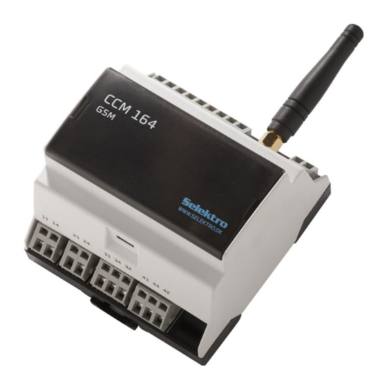
CCM 164 is a control and monitoring module with analog and digital inputs and relay outputs. All inputs and
outputs can be monitored and controlled via SMS (Short Message Service) or via a smartphone app. The
network is defined by the service provider's SIM card.
o An analog 4-20 mA input.
o Six digital (24 VDC) or analog (0-10 V) inputs.
o Four relay outputs - two power relays and two switching relays.
The User Manual can be retrieved from
This manual complies from firmware version 2.0.x.
Selektro A/S, Erhvervsvej 29-35, DK-9632 Møldrup, Denmark
CCM 164 – User Manual – GB / US
CCM 164
Communication and Control Module
www.selektro.dk/ccm
Copyright Selektro A/S 2018
under Manuals.
0881-1344005 V06
Advertisement
Table of Contents

Related Manuals for Selektro CCM 164

Summary of Contents for Selektro CCM 164
- Page 1 Communication and Control Module CCM 164 is a control and monitoring module with analog and digital inputs and relay outputs. All inputs and outputs can be monitored and controlled via SMS (Short Message Service) or via a smartphone app. The network is defined by the service provider’s SIM card.
-
Page 2: Table Of Contents
Deleting counter values of inputs ....................19 Good to know… ........................... 20 13.1. Removing a PIN code from a SIM card ..................20 13.2. Retrieving the module’s status information ................20 CCM 164 – User Manual – GB / UK... - Page 3 Special functions ..........................31 Firmware update ..........................32 Responsibility and guarantee ......................34 18.1. Responsibility for CCM 164 and its use ..................34 18.2. Guarantee ............................ 34 Electrical specifications ........................35 CCM 164 – User Manual – GB / UK...
- Page 4 Installation and use must be in accordance with applicable rules and good practice. Warning The module must not be placed in a dangerous explosive area or in close proximity to medical equipment. CCM 164 – User Manual – GB / UK...
-
Page 5: Description Of The Control Lamps, Buttons And Sim Card
LED is turned off. Slow flashing MODEM is ready with NET connection. Two quick flashes SIM card error. Quick flashing GSM network error. Turned off MODEM is turned off. 50% on/off flashing Modem transmitting CCM 164 – User Manual – GB / UK... -
Page 6: Button
1.3. SIM card Newer versions of the CCM 164 hardware (V2) uses SIM card Nano 12.3 x 8.8 mm type and is compatible with 1.8V and 3V SIM cards. Older versions of the CCM 164 hardware (V1) uses SIM card Mini 85.6 x 53.98 mm type and is compatible with 1.8V and 3V SIM cards. -
Page 7: Connection
31 – 32 is break (NC). Relay contact set 4, terminal 41 – 44 is closure (NO) and 41 – 42 is break (NC). For further technical details refer to “19. Electrical specifications”. CCM 164 – User Manual – GB / UK... -
Page 8: Getting Started
13. Good to know… o Counters 12. Counters, times, number of SMS sent and more o Special functions 16. Special functions o Short form instructions 15. Overview of commands (short form) CCM 164 – User Manual – GB / UK... -
Page 9: Module Name
Module name There may be multiple controllers each with their own CCM 164 module. A module name can be added so that it appears at the start of the SMS messages that are sent from the module. 5.1. Adding/modifying the module’s name <name>... -
Page 10: Telephone Book
Telephone book CCM 164 has a telephone book that includes a list of up to eight telephone numbers [P1...P8]. These telephone numbers can be configured to receive messages from the module. If the module is locked, then only the numbers in the telephone book will be capable of communicating with the module. (Refer to section “13.3. -
Page 11: Deleting Numbers In The Telephone Book
#Pn 0 0 = delete o Example : Position 3 in the telephone book is to be deleted send reply #P3 0 OK: P3 deleted CCM 164 – User Manual – GB / UK... -
Page 12: Current Input
Set up the current input for 0-10m water level: send reply #AI1 (water) R0.1 Um L0.0 H10.0 OK: AI1 defined 8.2. Readout value on current input Readout value on current input: send reply #AI1 ? Water = 2.0m CCM 164 – User Manual – GB / UK... -
Page 13: Digital Input
16 characters max. Characters not allowed: # [ ] ( ) Digital input. 9.1. Setup of digital input send reply #I1 (Lamp 1) D OK: I1 defined 9.2. Readout value of digital input send reply #I1 ? Lamp 1 = ON CCM 164 – User Manual – GB / UK... -
Page 14: Voltage Input
#I1 (pressure) R0.01 Ubar L0.00 H10.00 OK: I1 defined 10.2. Readout value of voltage input Readout value on input 1 set up as voltage input: send reply #I1 ? pressure = 5.00bar CCM 164 – User Manual – GB / UK... -
Page 15: Rules
Rules CCM 164 can be programmed with up to 16 rules. These rules can be set up to activate changes in the output states or activate sending of SMS messages to one or more recipients in the telephone book. 11.1. - Page 16 +4530303030. o First set up the new phone number. send reply #P3 +4530303030 OK: P3 defined o Create rule 2 send reply A2 (Door is closed) !I4 P13 OK: A2 defined CCM 164 – User Manual – GB / UK...
-
Page 17: Rules Overview
To get an overview of which rule positions are already in use, the module can return a message with a list of the active rules. #A ? Note: An empty message will be returned if there are no active rules. o Example: send reply Defined rules: #A ? A1 A2 CCM 164 – User Manual – GB / UK... -
Page 18: Retrieve Rule Definition
Rules can be deleted one at a time with the following command: m = [1..16] rule position number #Am 0 o Example: You wish to delete rule number 2 (Door is closed). send reply #A2 0 OK: A2 deleted CCM 164 – User Manual – GB / UK... -
Page 19: Counters, Times, Number Of Sms Sent And More
When reading time the d represents days. The numbers are stored in the module’s permanent memory every tenth minute, and as a result the precision is not better than every tenth minute. CCM 164 – User Manual – GB / UK... -
Page 20: Good To Know
Retrieving the module’s status information CCM 164 has a status message that informs of the model name, version number, active functions, the time the module has been connected to the power network, as well as whether the module’s configuration is locked or open for change. -
Page 21: Manually Unlocking The Configuration
Example configuration of messages in case of Net power fallouts: #I200 (Net power on) (Net power off) P1 10 10 By using the configurations above it is ensured that messages are transmitted from the CCM 164 when the Net power falls out and when it comes back on. -
Page 22: Locking Of The Module
Problem resolving (troubleshooting) It is always best to be located at the CCM 164 module when resolving problems. This allows for controlling that power is supplied and that there is sufficient GSM coverage. In many situations it is possible to tackle problems using simple SMS requests. - Page 23 After the procedure above it is validated by inspecting the STATUS LED whether the module is ok by e.g. sending the #sys info. If the module still returns “ERROR in EEPROM” please see 18 Responsibility and guarantee CCM 164 – User Manual – GB / UK...
-
Page 24: Overview Of Commands (Short Form)
E.g. #Q6 ON Error command unknown: #Q6 ON o If the command is recognized but a parameter contains an error “Error in command parameter” is returned: E.g. #LANG BT Error in command parameter: BT CCM 164 – User Manual – GB / UK... - Page 25 High value at 20mA {-99999..99999}. E.g. 10m H10.00 <high> #AI1 (Level) R0.01 Um L0.00 H10.00 OK: AI1 defined #AI?? #AIn (txt) R<resolution> U<unit> L<low> H<high> #AI1?? #AI1 (Level) R0.01 Um L0.00 H10.00 #AI1? #AI1 ? Level = 2m CCM 164 – User Manual – GB / UK...
- Page 26 #I200 (Power on) (Power off) P1 10 10 OK: I200 defined #I200?? #I200 (Power on) (Power off) P1 10 10 #I200? #I200 ? I200 = OFF Delete #I200 0 OK: I200 disabled CCM 164 – User Manual – GB / UK...
- Page 27 #Qn (txt) or #Qn <niveau> <ON tid> #Q1?? #Q1 (Lamp 1) #Q1? #Q1 ? Lamp 1 = ON ON OFF OFF OFF #Q ? Q1 = ON Q2 = OFF Q3 = OFF Q4 = OFF CCM 164 – User Manual – GB / UK...
- Page 28 5) AI2>5 #A?? #An (txt) <condition> <action> #A1?? #A1 (Level above 5) AI1>5 Q1D10 Q2 TQ3 =Q4 #A1? #A1 ? Level above 5 = OFF Delete #A1 0 OK: A1 deleted CCM 164 – User Manual – GB / UK...
- Page 29 System Commands Set default values #sys defaults #sys defaults OK: Sys Defaults Descriptions Set configurations to default values. Restart module #sys restart #sys restart The module does not reply to this command CCM 164 – User Manual – GB / UK...
- Page 30 A8=OFF A9=OFF A10=OFF A11=OFF A12=OFF A13=OFF A14=OFF A15=OFF A16=OFF Signal Strength (telephone network) #sys signal #sys signal RSSI = -<network RF signal level>dBm Description Received signal strength indication, range -51dBm (very good) to -113dBm (very bad). CCM 164 – User Manual – GB / UK...
-
Page 31: Special Functions
The period between the messages is set by Z19 see 15 Overview of commands (short form). #sys func x off x = [1..2] deactivates special function x. CCM 164 – User Manual – GB / UK... -
Page 32: Firmware Update
Windows 7 or newer, and a Micro-USB cable for connection between the PC and the CCM 164: Before you start the firmware update, it is important that you have a backup of the CCM 164 settings. I.e. programmed telephone numbers, messages, and other settings. A firmware update typically resets the settings in the module, and therefore must be manually set up again after the update. - Page 33 If this did happen, then it is necessary to disconnect the power and wait until the backup battery has fully discharged (all LEDs are off). Make sure that the USB cable is connected between the CCM 164 and the PC. Connect the power to the CCM 164 and open the ”Selektro Firmware Updater” PC tool.
-
Page 34: Responsibility And Guarantee
SMS with the programmed text is sent to the programmed telephone numbers. The module can, upon receipt of an SMS, start and close four relay outputs. The CCM 164 module will send a message if power from the power grid (230 VAC) is lost. -
Page 35: Electrical Specifications
4 … 20mA o Input impedance Approx. 100Ω o Error limit +/- 1% at FS Input range [min/max] 0…24mA, 0…30VDC Input frequency Max. 10Hz Line Length: Max. 100m CCM 164 – User Manual – GB / UK... - Page 36 Switching rate Max. 10Hz Line length Max. 100m Power supply output +V: Output voltage 24VDC Tolerance +/-20 % Output current Max. 100mA GSM / Antenna: Gain 0dBm CCM 164 – User Manual – GB / UK...
- Page 37 GSM/GPRS Quad-band GSM - 850/900/1800/1900 MHz UMTS/HSPA Dual mode UMTS/GSM -850/900/1800/1900/2100 MHz (special 3G version) Connector on module SMA female CCM 164 – User Manual – GB / UK...
Need help?
Do you have a question about the CCM 164 and is the answer not in the manual?
Questions and answers