Table of Contents
Advertisement
Quick Links
Advertisement
Table of Contents

Related Manuals for Intech Instruments IN-P Series


Summary of Contents for Intech Instruments IN-P Series
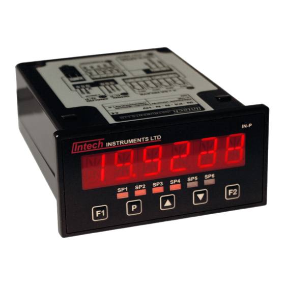
- Page 1 IN-P Multifunction Process Indicator Installation Guide.
-
Page 2: Table Of Contents
IN-P Installation Guide Index. SECTION 1. – Description and Ordering Information. Page 3 SECTION 2. – Specifications. Page 4 SECTION 3. – Case Schematics. Page 4 SECTION 4. – Input Jumper Configuration. Page 5 4.1 – Position your input Jumpers. Page 5 SECTION 5. -
Page 3: Section 1. - Description And Ordering Information
IN-P Multifunction Process Indicator. (was IN-P4) SECTION 1. – Description. The IN-P Multifunction Process Indicator interfaces smoothly with a wide range of PLC and monitoring systems. Designed specifically for use in process applications, this indicator accepts a variety of inputs. The IN-P can be configured for many different analogue inputs and functions as listed below. -
Page 4: Section 2. - Specifications
SECTION 2. – Specifications. Power supply HV: 85~265Vac / 95~370Vdc or LV: 15~48Vac / 10~72Vdc. Sampling rate 10Hz. Resolution 16-bit. Accuracy 0.05% of reading. Temperature drift Typically 50ppm/°C. Calibration Factory pre-calibrated - automatic or manual user calibration available. Security Setup is PIN code protected. Case 48 x 96 x 119.5mm (H x W x D) / 45.5 x 92.5mm panel cutout. -
Page 5: Section 4. - Input Jumper Configuration
3.2 – Fig 2 - Rear view: CONNECTOR PINS: G - Relays Wiring: Section 5.3 H - Serial port Wiring: Section 5.5 I - Analogue output Wiring: Section 5.4 J - IP07 input module Jumper setup: Section 4 Wiring: Section 5.2 K - Function pins Wiring: Section 5.6 L - Power supply (HV LV) Wiring: Section 5.1... -
Page 6: Section 5. - Wiring
SECTION 5. – Wiring. Before you Begin: Determine whether your indicator is configured for low or high voltage power supply. Make sure to check the label on the unit against the colour of the power connector: Orange = High voltage HV (85~265Vac / 95~370Vdc). Black = Low voltage LV (15~48Vac / 10~72Vdc). -
Page 7: Wire Your Function Pins (If Required)
5.6 – Wire your function pins (if required): Refer to 3.2K Connect external switches to enable a function to be executed when its switch is activated. Valley Clears the valley reading. Hold Hold the current display value. Test Reset the meter. Peak Clears the peak reading. -
Page 8: Averaging
If you selected AUTO in 6.3A: _ _ _ APPLY LOW INPUT SIGNAL – – – – ENTER LOW DISPLAY VALUE scrolls across the display. Apply the required low input signal to the indicator. Using the and buttons, enter your low end display value. Then press P to accept. -
Page 9: Serial Setup
_ _ _ CAL LOW ANALOG OUTPUT scrolls across the display and toggles with a calibration number. Using the and buttons, calibrate your low analogue output as required. Then press P . The display value is shown in internal units (mA). _ _ _ CAL HIGH ANALOG OUTPUT scrolls across the display and toggles with a calibration number. -
Page 10: Section 7. - Setpoint Setup
SECTION 7. – Setpoint Setup. Note: To SKIP or ENTER values - Push Enter the setpoint setup mode by pressing and holding the button for 3 seconds. To SELECT a menu input - Push 7.1 – Enter setpoint PIN: ALARM CNTRL (Control) The setpoint value determines setpoint activation, and The setpoint value determines setpoint deactivation, and... -
Page 11: Edit Setpoint Pin
7.3 – Edit setpoint PIN: _ _ _ EDIT SP PIN NUMBER? scrolls across the display and toggles with SKIP. Press P to skip and return to the operational display, or the button and then P to ENTER. _ _ _ ENTER NEW SP PIN NUMBER scrolls across the display and toggles with the current PIN (default = 1). - Page 12 www.intech.co.nz Christchurch Ph: +64 3 343 0646 Auckland Ph: 09 827 1930 Email: sales@intech.co.nz IN-P 071216...
Need help?
Do you have a question about the IN-P Series and is the answer not in the manual?
Questions and answers