
Related Manuals for FE NRF50


Summary of Contents for FE NRF50
- Page 1 User’s Manual Electronic Personal Dosimeter NRF50 Fuji Electric Co., Ltd. TN5A2293 1/37...
- Page 2 This User’s Manual is a document to explain the operation of the Electronic Personal Dosimeter NRF50 sample unit briefly. It is organized to provide descriptions of parts, functions and operational instructions for optimal use. Please make sure that you read this manual carefully before operation. If there are some requirements or improvements about this sample unit, please contact Fuji Electric representative.
- Page 3 Handling Precaution Please read the following handling precautions to ensure that you use the sample unit safely and avoid injury/damages. Please read this User’s Manual carefully to understand all the precautions before using the sample unit. Measures of Precaution ・ The Dosimeter is a precision instrument; do not drop it or subject it to impact. ・...
-
Page 4: Table Of Contents
Contents Overview ............................5 Contents ............................6 Sample unit package ........................6 Model ............................. 6 Precaution ............................7 Operational conditions ........................7 Other requirements ........................7 Description of Parts and Functions ....................8 Part names ............................ 8 Display function ........................... 10 Buzzer function ........................... -
Page 5: Overview
Using the Setting Device and a PC, it is able to write PC-edited values to NRF 50 and read measurement trend data from the NRF50 via communication with the device. If worn tight to the body, energy characteristic of the NRF50 enables direct reading of personal dose equivalent Hp(10). (unit: rem) -
Page 6: Contents
Contents Sample unit package (1) NRF50 (2) Accessory ・Battery (AA alkaline battery) Model NRF50 TN5A2293 6/37... -
Page 7: Precaution
(1) See User’s Manual of “Setting Device” for information on parameter writing and data reading via the device and a PC. (2) Try turn OFF & ON the NRF50 if you encounter technical problems. See the “Troubleshooting Table” if not recovered. -
Page 8: Description Of Parts And Functions
Description of Parts and Functions Part names Auxiliary LED Flash LED Right Side Front Back Left Side Battery Cap Call Button Call Type NRF50 Serial No.****** Fuji Electric Co.,Ltd. Operating Button USB Connector Calibration Mark Buzzer EPD Information TN5A2293 8/37... - Page 9 :For communication with infrared communication device. 9. IR :Emergency alarm button. Press for more than 3 seconds to 10. Call Button generate warning sound and indication. :For indicating model and serial number of the NRF50. 11. EPD Information TN5A2293 9/37...
-
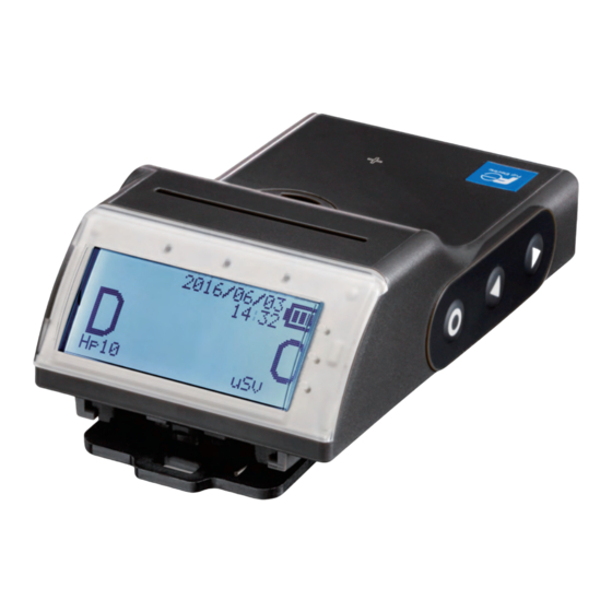
Page 10: Display Function
Display function LCD Indication ■Normal condition Icon area Date indication※ Battery remaining Accumulated d:Accumulated dose dose R:Dose Rate Dose rate Unit ■Alarm condition Icon area Battery remaining Date indication※ Accumulated dose d:Accumulated dose Dose rate R:Dose Rate Unit Warning info ※During normal operation, “:”... -
Page 11: Buzzer Function
NRF50 is turned off No sound Contact to setting Communication starts. No sound device Data transmission Successful completion of data transmission No sound Setting values of NRF50 are changed using a No sound setting device. Data transmission failed No sound TN5A2293 11/37... - Page 12 4.3.2 Audible alarms Alarm activations and beep patterns are as follows: ① Dose value alarm Alarm type LCD indication Buzzer Vibration Alarm for Sounds 3 times Vibrates 1 time Flashes 1 time accumulated dose per 1 second per 1 second per 1 second Alarm:...
- Page 13 ③ Low battery voltage Alarm type LCD indication Buzzer Vibration Low battery Sounds 3 times No vibration Flashes 1 time voltage per 10 minutes per 10 minutes (Short sound) Auxiliary LED (RED) Operating time Buzzer ④ Indication of abnormality Alarm type LCD indication Buzzer Vibration...
- Page 14 4.3.3 Monitoring Sound Buzzer sounds 1 time, if accumulated dose reaches a preset value of dose interval for monitoring sound. Monitoring sound interval can be chosen from 6 types such as “OFF”, “10mrem”, “1mrem”, “0.1mrem”, “8 counts” and “4 counts”. Please see User’s Manual of “Setting Device” for details. TN5A2293 14/37...
-
Page 15: Parts Replacement
(Both batteries are positioned in the same direction) (4) Close tighten with screwdriver. ① When replacing batteries, make sure to turn off NRF50. ② During replacement, align the battery polarity correctly. Attention ③ Use only AA Alkaline battery. TN5A2293 15/37... -
Page 16: Operational Instruction
Operational Instruction When starting to use (1) Press and hold “◎” button for more than 3 seconds to start the NRF50. Confirm the power is ON (one beep) and LCD. In case NRF50 is left without battery for more than 1 day Normal condition DATE SETUP &... - Page 17 “△” or “▽”. “◎” button can also switch the display to other screens. Please see section 6.2 in details for screen change methods by “◎” button. (3) Put NRF50 in the chest pocket as shown below. ① When putting in an outside pocket...
-
Page 18: During Use (Normal Operation)
During use (Normal operation) LCD display during operation of button ※LCD display will be changed when pressing the designated button with backlight flashed. Display Remarks 【Basic display】 Power turns off by long ⇒To No.2 press of “◎” button. (Basic display or number indicating display) Indication is changed by short press of “△”... - Page 19 Display Remarks 【Number indicating display】 Switching Power turns off by long press of “◎” button. Short press of “▽” EPD number indication Short press of “▽” Short press of “△” ID number indication Short press of “▽” Short press of “△” RWP number indication Short press of “△”...
- Page 20 Display Remarks 【Setting Display】Switching Long press of “◎” to change each display. Short press of “▽” 08/ 20/ 2014 Configuration 10: 35 Hp10 Long press of “◎” to m r em change display for setting CONFI G items Short press of “△” ⇒ To No.5 Short press of “▽”...
- Page 21 Display Remarks 【Setting items display】Switching Short press of “◎” to change set values. (Yellow backlight turns Short press of “▽” Long press of “◎” to confirm the change. Name setting Name can be entered with 10 characters from A to Z. Short press of “▽”...
- Page 22 Display Remarks 【Setting items display】Switching (continued) Change a set value for each items by short press of “◎”. (Yellow backlight from the previous page turns on) Short press of “▽” Confirm the change by long press of “◎”. Alarm setting, date and Operating time time setting can be set alarm setting...
- Page 23 TN5A2293 23/37...
- Page 24 Display Remarks 【Setting items display】Switching (continued) from the previous page Short press of “▽” Short press of “△” Version (Only confirmation) Short press of “▽” Short press of “△” Setting completed Return to setting display ⇒ To No.4 by short press of ”◎”. Short press of “△”...
- Page 25 Display Remarks 【Memorandum】 Return to setting display by long press of “◎”. Memo display (1 to 10 characters) Short press of “▽” Short press of “△” Memo display (11 to 20 characters) Short press of “▽” Short press of “△” Memo display (21 to 30 characters) Short press of “▽”...
-
Page 26: During Use (When Alarm Is Generated)
During use (When alarm is generated) LCD display when generating alarm ※See Chapter 4 for operation of buzzer, vibration and LED during alarm generation. Item Display Remarks Accumulated dose alarm Alarm Preliminary alarm is generated, when exceeding warning set value. Alarm is generated, when exceeding alarm set value. - Page 27 Item Display Remarks Detector optical error When detector cannot work properly for internal optical pulse check by internal LED, detector optical error alarm is generated. Memory error When not affecting counting When memory failure occurs during data backup, memory error alarm is generated.
-
Page 28: During Use (When Communicating)
During use (When communicating) LCD display during communication Item Display Remarks Infrared communication “IR” is displayed on the upper left of screen during infrared communication. USB communication Icon does not appear 08/ 20/ 2014 10: 35 during USB 0 0 . communication. -
Page 29: Care And Maintenance
Care and Maintenance Check the NRF50 as specified below to ensure quality performance. Daily check and maintenance items Check items Procedures Check point Appearance Check the NRF50 visually. No signs of crack, damages or breakage on the case. No signs of When to check;Before use and after battery... -
Page 30: Specification
Specification General Specification Model : NRF50 Category : Grade 1 Detector : Silicon semi-conductor : γ(X) rays (30 keV to 7.0 MeV) Radiation type Dose display range: 0.1 mrem to 1000 rem, 0.1 mrem/h to 1000 rem/h Effective measurement range: 2.0 mrem to 1000 rem, 0.05 mrem/h to 1000 rem/h (accumulated dose) 10.0 mrem/h to 1000 rem/h (dose rate) -
Page 31: Storage Data
Storage data ① List of storage data (Updated value is stored in EEPROM every 1 minute) ・EPD number ・Current time ・Current accumulated dose ・Current dose rate ・Operating time ・Alarm setting values (Accumulated dose, Dose rate : 2 for each) ・Time alarm setting value ・Calibration factor ・Error flag ・Condition flag... -
Page 32: Appendix
Appendix Trouble shooting table Error Indication Possible Cause Suggested Solution 「OPTI ERROR」 (1)Sensor unit malfunction (1),(2) (2)CPU malfunction Contact Fuji Electric representative. 「MEM ERROR」 (1)EEPROM malfunction (1),(2) (2)CPU malfunction Contact Fuji Electric representative. 「RTC ERROR」 (1)RTC malfunction (1),(2) (2)CPU malfunction Contact Fuji Electric representative. -
Page 33: Disposal
(1) Communication distance is too far (1) Set the distance between unable. (2) Communication port is dirty. Communication port of NRF50 and the (3) CPU malfunction Setting device within 5cm. Also confirm that (4) Malfunction of setting software these windows are face to face. -
Page 34: Calibration
Cs and A dose should be measured by placing the source at a certain distance (calibration distance) from reference point of NRF50 so that true value of the dose is traceable to the National Sta ndard. (1) Determination of a reference dose rate value (R... - Page 35 (3) Calculation of the calibration factor - Compare the reference dose (R ) and the dose reading (R ). If there is an unacceptable difference between R and R , change the calibration factor. In general, the calibration factor (C ) is calculated by the following formula: ×...
-
Page 36: Block Diagram
Block diagram CPU unit Battery Voltage monitor circuit battery 1.5V AA x 2 Dots Main power LED backlight power ON/OFF control Transponder Coil Wireless module VBUS voltage down power ON/OFF control converter Magnetic Communication Module Circuit Piezoelectric Buzzer Module Buzzer drive Buzzer power circuit LED unit... - Page 37 Any comments/ requests/ suggestions regarding our instruction manual? Please feel free to contact us by filling out this form and give to our sales representative. Document No TN5A2293 Date year month day Company Name of Electronic Personal Dosimeter NRF50 Submitted Dept manual User’s Manual Name Page Line...