Sign In
Upload
Download
Table of Contents
Contents
Add to my manuals
Delete from my manuals
Share
URL of this page:
HTML Link:
Bookmark this page
Add
Manual will be automatically added to "My Manuals"
Print this page
×
Bookmark added
×
Added to my manuals
Manuals
Brands
FE Manuals
Measuring Instruments
FSH
Instruction manual
FE FSH Instruction Manual
Hybrid ultrasonic flowmeter
Hide thumbs
1
2
3
4
5
Table Of Contents
6
7
8
9
10
11
12
13
14
15
16
17
18
19
20
21
22
23
24
25
26
27
28
29
30
31
32
33
34
35
36
37
38
39
40
41
42
43
44
45
46
47
48
49
50
51
52
53
54
55
56
57
58
59
60
61
62
63
64
65
66
67
68
69
70
71
72
73
74
75
76
77
78
79
80
81
82
83
84
85
86
87
88
89
90
91
92
93
94
95
96
97
98
99
100
101
102
103
104
105
106
107
108
109
110
111
112
113
114
115
116
117
118
119
120
121
122
123
124
125
126
127
128
129
130
131
132
133
134
135
136
137
138
139
140
141
142
143
144
145
146
147
148
149
150
151
152
153
154
155
156
157
158
159
160
161
162
163
164
165
166
167
168
169
170
171
172
173
174
175
176
177
178
179
180
181
page
of
181
Go
/
181
Contents
Table of Contents
Troubleshooting
Bookmarks
Table of Contents
Preface
Safety Precaution
Caution on Installation Location
Table of Contents
Product Outline
Outline
Measurement Principle
Checking Delivered Items
Checking Type and Specifications
Names of each Part and Functions
Selecting Installation Location
Flow Transmitter
Detector
Length of Straight Section of Pipe
Mounting Position
Mounting the Sensor
Installation and before Start of Operation
Before Operation
Installing the Flow Transmitter
Flow Transmitter Wiring
Cautions in Wiring
Applicable Wires
Treatment of Wiring Port
Removing and Mounting the Cover and the Shield Plate
Wiring to each Terminal
Setting Piping Parameters and Calculating the Sensor Spacing
Selecting Sensor Type, Mounting the Sensor, Setting the Sensor Constant
Entering Piping Specifications
Installing Detector
Outline of Detector Installation Procedure
Treatment of Mounting Surface
Mounting the Detector by Z Method Using the Frame
Mounting the Sensor Unit by Z Method Using a Frame (2 Measurement Lines)
Mounting the Sensor Unit to a Large-Diameter Pipe
Setting Analog Output Range and Total Pulse
Analog Output Range Setting
Total Pulse Output Setting
Zero Adjustment
Setting Parameters
Description of Display/Setting Unit
Description of Display
Description of Keys
Setting Item List
Parameter Specification Table
Setting Parameters
Measurement Method and Sensor
Pipe Specifications
Measurement Mode (Measurement Mode, AO Definition)
Output Setting
Range (Range Unit, Range Type, Full Scale, Hysteresis) Setting
Output Limit
How to Set Analog Output at Error (BURNOUT)
Rate Limit
Damping
Zero Adjustment
Display Setting
Cut off
Integration
Total Unit
Setting Total Pulse (Total Rate, Pulse Width)
Total Preset
Total SW
Determining How to Dispose of Total at Error (BURNOUT)
Flow Switch
Status Output
Output Calibration
Measurement Unit
System Language Selection
Setting Serial Communication (RS232C/RS485)
Maintenance
Analog Output Adjustment and Check
Checking Status Output
Calibrating Temperature Sensor
Checking Temperature Sensor
Test Mode
LCD Backlight
Key Lock
Checking System Name
Details of Measurement
Transit Time
Pulse Doppler
Initializing Setting Parameters
Confirmation of Software Version
Maintenance and Inspection
Daily Inspection
Periodic Inspection
Checking Zero Point
Calibrating Current Output Circuit
Calibrating Temperature Sensor Circuit
Measuring Insulation Resistance
Replacing Fuse
Replacing Relay
Replacing LCD
Troubleshooting
How to Confirm Normal Operation
Checking on LCD
Checking Measurement Status Information
Checking and Setting of RAS Information
Status Information
Measurement Data Information
Faults and Remedies
Display Error
Key Failure
Measurement Value Error
Analog Output Error
Checking Received Waveform
Method by Oscilloscope
Checking Signal Waveform (TRANSIT TIME)
Checking Demodulated Waves (Pulse Doppler)
Measures against Hardware Failure
Pc Loader Software
Copyright of this Software
Outline
PC to be Used
Computer
Memory Capacity
Interface
Installing of Software
Startup Method
Communications
Setting
Save Setting
Read Setting
Version
Structure of Function
Establish Setting
Range Setting
Total Setting
Status Output Setting
Display Setting
System Setting
Measurement
Pulse Doppler Measurement
Detailed Setting (Optional Function)
Flow Velocity Profile (Optional Function)
Operation Information
Transit Time Difference Measurement
Detailed Setting (Optional Function)
Received Signal (Optional Function)
Operation Information
Maintenance
End
Uninstalling of Software
Appendix
External Communication Specifications
Communication Specifications
Message Configuration
Receiving
Response
Error Response
Error Check
Function Code Table
Error Code Table
Cable Connection Specifications (RS-232C)
Specifications
Outline Diagram
Items to be Specified at Placement of an Order
Composition of Key Operation
Piping Data
Making Gauge Paper
Advertisement
Quick Links
Download this manual
Instruction Manual
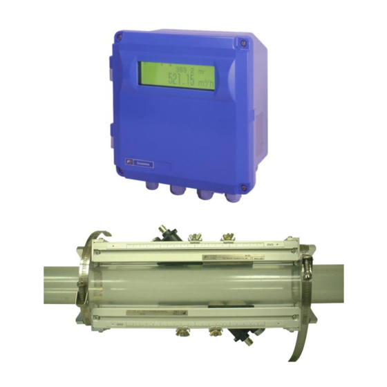
HYBRID
ULTRASONIC FLOWMETER
<Duosonics>
TYPE: FSH (Flow transmitter)
FSW (Detector)
FLY (Signal cable)
INF-TN1FSHa-E
Table of
Contents
Previous
Page
Next
Page
1
2
3
4
5
Advertisement
Table of Contents
Need help?
Do you have a question about the FSH and is the answer not in the manual?
Ask a question
Questions and answers
Related Manuals for FE FSH
Measuring Instruments FE FLY Instruction Manual
Hybrid ultrasonic flowmeter (181 pages)
Measuring Instruments FE NRF50 User Manual
Electronic personal dosimeter (37 pages)
Measuring Instruments FE PHW Quick Reference
Paperless recorder (12 pages)
This manual is also suitable for:
Fsw
Fly
Table of Contents
Print
Rename the bookmark
Delete bookmark?
Delete from my manuals?
Login
Sign In
OR
Sign in with Facebook
Sign in with Google
Upload manual
Upload from disk
Upload from URL


Need help?
Do you have a question about the FSH and is the answer not in the manual?
Questions and answers