
Related Manuals for ACE COMPUTERS PWB411

Summary of Contents for ACE COMPUTERS PWB411
- Page 1 PWB411 and PWB421 Blade Servers User Manual Revision 1.0 Revision Date: 03.18.2022...
- Page 2 Please Note: For the most up-to-date version of this manual, please see our website at www.acecomputers.com. Ace Computers reserves the right to make changes to the product described in this manual at any time and without notice. This product, including software and documentation, is the property of Ace Computers and/ or its licensors, and is supplied only under a license.
- Page 3 If you have any questions regarding this manual or server system, please contact our support team through Ace Computers Support page https://acecomputers.com/support/ .This manual may be periodically updated without notice. Please check the Ace Computers website for possible updates to the manual revision level. ACE097 Page 3 of 23 Rev Date:3.18.2022...
-
Page 4: Table Of Contents
Table of Contents Table of Contents Chapter 1 – Testing/Compatibility Information ...................5 Operating Condition Class ......................... 5 Compatible Chassis’ ........................... 5 Chapter 2 - Illustrated System Disassembly Instructions ..............6 Data Storage Devices ......................... 7 Memory ............................. 8 Processor ............................9 Motherboard ........................... -
Page 5: Chapter 1 - Testing/Compatibility Information
A2 without becoming materially affected would be 70,080 hours. 2. Compatible Chassis’ The table below indicates the chassis that would qualify the associated blade server as being Energy Star qualified. Blade Server Compatible Chassis PWB411 PWBC82H822 PWB421 ACE097 Page 5 of 23 Rev Date:3.18.2022... -
Page 6: Chapter 2 - Illustrated System Disassembly Instructions
Chapter 2 - Illustrated System Disassembly Instructions Chapter 8 is intended to provide guidance to recyclers on the presence of materials and components at the product/family level, per Article 15 of the EU WEEE Directive 2012/19/EU. The provided information should also help direct recyclers to proper methods for removing parts and general product disassembly instructions. -
Page 7: Data Storage Devices
1. Data Storage Devices Location: Servers are best known for their storage and interchangeability, this is most commonly done through front hard drive bays as noted in the photo below. Some servers may also have SSD storage, this type of storage can be found on the motherboard. It generally lays flat, parallel to the board, rather than at a right angle. -
Page 8: Memory
Memory Location: Memory modules are found on the motherboard of the server, the number of memory modules may vary by unit configuration but are generally found in pairs of 2. Type and number of fastenings: Two (2) latches per memory module. Tools required: None. -
Page 9: Processor
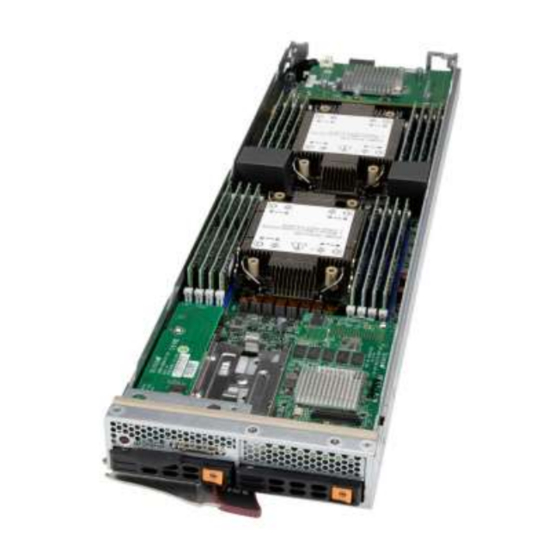
3. Processor Location: The processor is found on the motherboard of the server. As shown in the photo below, the processor is located under the heat sink. The heatsink can look more like a fin type thermal transfer device, or a rotating fan with a thermal transfer plate. There can be more than one processor per motherboard. -
Page 10: Motherboard
4. Motherboard Location: The motherboard is generally centrally located within the unit. Standard practice would be to remove all the components, peripherals, and add-ons from the motherboard before removal of the motherboard for processing. Type and number of fastenings: 10 Phillips screws. Tools required: Screwdriver with PH2 bit. -
Page 11: Ssd Drive
5. SSD Drive Location: Certain configurations of server may include a SSD drive. It is used for add-on types of components; it is attached directly to the motherboard. Type and number of fastenings: One (1) socket located on the motherboard and one (1) plastic plug Tools required: None. -
Page 12: Blade Chassis Cover
6. Blade Chassis Cover Location: The chassis cover is located on the upright, top side of the server, and it approximately 2/3 the size of the entire top, as noted in the illustration below. Type and number of fastenings: One (1) Phillips Head Screw. Tools required: Phillips Head Screw Driver. -
Page 13: Batteries
7. Batteries Location: The battery is located on the motherboard, see illustration below. Type and number of fastenings: One (1) latch. Tools required: None. Procedure: Push aside the small clamp that covers the edge of the battery. When the battery is released, lift it out of the holder. -
Page 14: Chapter 3 - Installation, Maintenance And Replacement Instructions
Chapter 3 – Installation, Maintenance and Replacement Instructions This chapter provides instructions on installing and replacing main system components. To prevent compatibility issues, only use components that match the specifications and/or part numbers given. Installation or replacement of most components require that the power first be removed from the system. -
Page 15: Processor And Heatsink (Replacement/Installation)
Processor and Heatsink (Replacement/Installation) The processor (CPU) and processor carrier should be assembled together first to form the processor carrier assembly. This will be attached to the heatsink to form the processor heatsink module (PHM) before being installed onto the CPU socket. The Processor Carrier Assembly The processor carrier assembly is comprised of the processor and the processor carrier. - Page 16 3. Locate the lever on the carrier and, if necessary, press it down as shown below. 4. Align the CPU keys on the processor (A & B) with those on the carrier (a & b) as shown below. 5. Carefully place one end of the processor under latch 1 on the carrier, and then press the other end down until it snaps into latch 2 and is properly seated on the carrier.
- Page 17 The Processor Heatsink Module (PHM) After creating the processor carrier assembly, mount the heatsink onto the carrier assembly to form the processor heatsink module (PHM). Note: If this is a new heatsink, the thermal grease has been pre-applied. Otherwise, apply the proper amount of thermal grease to the underside of the heatsink.
- Page 18 Installing the PHM into the CPU Socket 1. Remove the plastic protective cover from the CPU socket. Gently squeeze the grip tabs then pull the cover off. 2. Locate the threaded fasteners (a, b, c, d) on the CPU socket. ACE097 Page 18 of 23 Rev Date:3.18.2022...
- Page 19 3. Locate four PEEK nuts (A, B, C, D) and four rotating wires (1, 2, 3, 4) on the heatsink as shown below. 4. Check the rotating wires (1, 2, 3, 4) are in the unlatched position as shown. 5. Align nut A (next to the triangles and pin 1) on the heatsink with threaded fastener “a” on the CPU socket.
-
Page 20: Memory (Replacement/Installation)
7. Press all four rotating wires outward to latch the PHM onto the CPU socket. 8. With a t30-bit screwdriver, tighten all PEEK nuts in the sequence of A, B, C, and D with even pressure not greater than 12 lbf-in. Memory (Replacement/Installation) Type and number of fastenings: Two (2) latches per memory module. -
Page 21: Data Storage Devices (Replacement/Installation)
Data Storage Devices (Replacement/Installation) Type and number of fastenings: HDD = two locking clasps, SSD = two locking clasps. Tools required: None. Procedure: 1. Remove the dummy drive, which comes pre-installed in the drive carrier. Pull out the two locking clasps on the left outside of the carrier and lift out the dummy drive. 2. -
Page 22: Ssd Drive (Replacement/Installation)
3.4 SSD Drive (Replacement/Installation) Type and number of fastenings: Plastic plug Tools required: None. Procedure: 1. Use industry-standard anti-static equipment, such as gloves or wrist strap, and follow precautions to avoid damage caused by ESD. 2. Insert the SSD into the socket on the motherboard. Then push it flat against the standoff. -
Page 23: Chapter 4 - Product Take-Back, End-Of-Life Processing, And E-Waste Program
Computers Team Member will reach out to further assist with your technical questions. If it is determined that the best course of action is an inhouse repair at Ace Computers, the service technician will help facilitate the process of returning the server for repair.
Need help?
Do you have a question about the PWB411 and is the answer not in the manual?
Questions and answers