Table of Contents
Advertisement
Quick Links
Advertisement
Table of Contents

Subscribe to Our Youtube Channel
Related Manuals for OLS CERO

Summary of Contents for OLS CERO
- Page 1 CELL CULTURE SIMPLIFIED |...
- Page 2 CERO_Operators Guide_Version 2018-12_01...
- Page 3 Greatest possible care was used on the correctness of the information in this Operators Guide. If errors should be discovered nevertheless, OLS is pleased to be informed about it. Regardless of this, OLS cannot assume any liability for errors in this Operators Guide or for their consequences.
- Page 4 With proper care and maintenance, your new CERO system will serve you faithfully. To learn about the proper care and maintenance of your investment, please take the time to read this Operators Guide.
-
Page 5: Table Of Contents
........................13 2.3 Electrical Safety Precautions ...................13 2.4 Biohazard Precautions ....................13 3. PRODUCT DESCRIPTION ................. 14 3.1 Culturing Cells in the CERO .....................14 3.1.1 Parameters, Protocol and Experiment ................. 14 3.1.2 Inoculations Protocol....................15 3.1.3 Culture Protocol ......................16 3.1.4 Harvesting Protocol ...................... 16 3.2 Allgemeine Beschreibung des CERO... - Page 6 5.5 Set CO Offset Compensation ..................30 5.6 Create a New Experiment ....................31 5.7 Insert a CEROtube in the CERO ..................32 5.8 Start an Existing Experiment ..................33 5.9 Follow-up a Running Experiments .................. 34 5.10 View the Output of a Previous Experiment ..............34 5.11 Export the Output Files of a Previous Experiment ............
- Page 7 6.4.8 Single Point Measurement during a Running Experiment ........... 52 7. MAINTENANCE ....................53 7.1 Weekly Maintenance ......................53 7.2 Decontamination of the CERO ..................53 7.3 Remove and Re-Install the Front Cover ................54 7.4 Remove and Re-Install the Convection Channel .............55 7.5 Replace Hepa Filters .......................55...
- Page 8 8.1.3 Temperature Unstable ....................58 8.2 CO Level ........................59 8.2.1 CO Alarm Triggered ...................... 59 8.2.2 CO Level Too High ......................59 8.2.3 CO Level Too Low ......................60 8.2.4 CO Level Unstable ......................60 8.2.5 CO Consumption Too High ................... 60 8.3 Tube Rotation Interrupted .....................
-
Page 9: Prologue
+ tips & tricks + troubleshooting Every effort has been made to ensure that all the information contained in the CERO Operators Guide is correct at the time of printing. However, OLS OMNI Life Science GmbH & Co. KG reserves the right to make any changes necessary without notice as part of ongoing product development. -
Page 10: Declaration Of Conformity
(Safety); EN 61326-:2013 (EMC Emision, Class B) and EN61326-1:2013 (EMC Immunity) IV. Warranty The warranty conditions are specified in the sales contract. Contact your OLS representative for further information. Any unauthorized modification of the instrument invalidates the guarantee and service contract. -
Page 11: General Information
After introducing you to the various parts of the CERO, we will show you step by step how to operate the instrument. When you have read this Operators Guide, you should be capable of operating the CERO. -
Page 12: Safety Precautions And Hazards
2.1 General Precautions 2.1.1 Instrument For safe and correct use of the CERO, it is essential that both operating and service personnel follow generally accepted safety procedures as well as the safety instructions in this document, the CERO Operators Guide. -
Page 13: Hazards Of Co
2.3 Electrical Safety Precautions The CERO must first be switched off and disconnected from the main electrical supply before removing any mechanical or electrical component. Do not connect the unit to a power source of any other voltage or frequency beyond the range stated on the power rating in the Technical Specifications (see Chapter 9). -
Page 14: Product Description
Harvesting (figure 1). Figure 1: Cu lturing Cells in the CERO – us ing th e ex ample of a microcarier culture The initial inoculation phase supports the aggregation of the cells or the loading of cells on the microcarrier substrate. The culture phase refers to the expansion of the culture. The harvesting phase (optional) corresponds to the dissolution of the cells. -
Page 15: Inoculations Protocol
3.1.2 Inoculations Protocol An Inoculation Protocol defines all necessary actions enabling cell aggregation or adherence/ loading on Microcarriers in the CERO and contains a defined set of parameters controlling the CEROtube movements (figure 2). The basic CEROtube movement supporting the... -
Page 16: Culture Protocol
3.1.3 Culture Protocol After a successful inoculation cell expansion is easily accomplished. The Standard Culture Protocols (figure 3) consist of the same parameters as the Inoculation Protocol. Since Culture Protocols usually do not need conditions as gentle as Inoculation Protocols, the default parameters have different settings e.g. -
Page 17: Allgemeine Beschreibung Des Cero
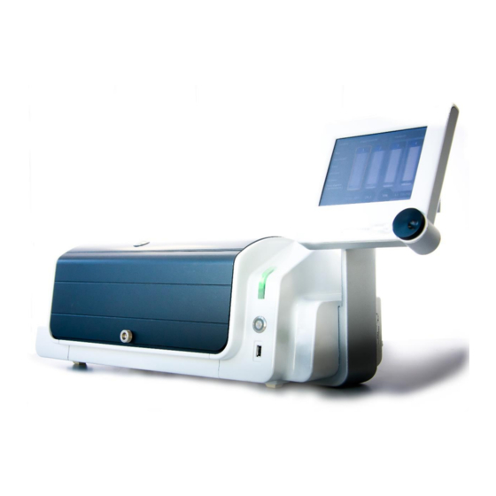
Removable Front cover Open Cover Button Figure 5: CERO Sys tem Overview The CERO components and accessories are further described in the following sections. 3.3 Culture Chamber 3.3.1 Sealed Culture Chamber The sealed compact Culture Chamber (figure 6) maintains consistent CO and temperature levels during cell expansion. -
Page 18: Co And Temperature Control
Figure 7: Control of CO -Level 3.3.3 Control of the Cell Suspension The CERO supports up to four independent and high density cell cultures. The CEROtubes have been designed to gently homogenise the cell suspension in the CERO through bidirectional rotation (figure 8). -
Page 19: User Interface
3.4 User Interface The Touch-Screen Interface with Click-Wheel (figure 9) allows for quick navigation and provides users with intuitive and easy to program cell culture workflows. In addition, culture reports (including temperature and CO monitoring) can be viewed real-time, saved and exported for records of compliance. -
Page 20: Cero Software
3.5 CERO Software The CERO Software is structured in 4 Menus all accessible from the Main Menu (see figure 10): - the System Menu - the Experiments Menu - the Outputs Menu - the Run Menu Figure 10: Menu Structu re... -
Page 21: Main Menu
3.5.1 Main Menu The Main Menu provides an overview of all cultures running in the CERO. The Temperature and the CO Control Windows in the Starting Page enable the control of the temperature and the level in the CERO. 3.5.2 Experiments Menu In the CERO, an Experiment consists in the succession of predefined protocols, usually an inoculation protocol followed by a culture protocol and a harvesting protocol. -
Page 22: Electronics
The use of inappropriate fuses can severly damage your instrument and become a shock or fire hazard. 3.6.3 Power On / Off Switch The Power On / Off Switch is a two-position rocker switch located on the back side of the CERO (figure 11). CERO_Operators Guide_Version 2018-12_01... -
Page 23: Open Cover Button
3.6.4 Open Cover Button The Open Cover Button is a round Button located on the front side of the CERO (figure 12). It controls opening and closing of the Sliding Top Cover. Status Indicator Open Cover Button USB Port Figure 12: Open Cover Bu tton and USB Port 3.6.5 Communications Ports... -
Page 24: Installation
4 INSTALLATION 4.1 Product Content The CERO comes with everything you need to start using the system. Part number Description 2800000 CERO including: • Convection Channel (Part number 2800003) • Hepa Filters (Part number 2800002) • Power Cable • CERO Operators Guide (Part number 624206) 4.2 Requirements... -
Page 25: Installation Pocedure
Connect the Mains Power Cable to the Mains Power Connector on the rear of the CERO. □ Connect the Mains Power Cable to the electrical outlet. NOTE We recommend connecting the CERO to an Uninterruptible Power Supply (UPS) to protect your cultures from potentially harmful uncontrolled power shutdowns. CERO_Operators Guide_Version 2018-12_01... - Page 26 4. Connect CO supply □ Connect the CERO to the low pressure side of a CO regulator using the appropriate Tubing (Tygon® Tubing with 3/16" (4.8 mm) inner diameter (figure 14). □ Make sure that the connection is tight and secure.
-
Page 27: Operation
5. OPERATION 5.1 Switch ON the CERO 1. Turn the CERO ON Power Switch on the side of the Instrument. 2. The Main Menu screen (figure 15) appears after a few minutes. Figure 15: Main Menu 5.2 Set Temperature 1. Enter the Temperature Control Window (figure 16) from the Main Menu. -
Page 28: Set Co 2
5.3 Set CO ATTENTION For safety reasons, we recommend to check the integrity of the CO supply before starting CO regulation. Do not start the CO regulation when the removable front cover is not in place. Do not start the CO regulation when the convection channel is not installed or damaged. -
Page 29: Set Temperature Offset Compensation
The Temperature Offset Compensation may be used to adjust the temperature to your specific standards, especially before the first operation of the instrument. 1. Place a CEROtube with 40 mL pre-warmed (37°) water in the position 2 of the CERO (see Chapter 5.7). -
Page 30: Set Co Offset Compensation
2. Allow the CO levels to stabilize for at least 20 minutes. 3. Insert a CO incubator analyser probe into the coin screw opening in the sliding cover of the CERO and measure the CO concentration. NOTE ® We recommend the use of the Vaisala’s CARBOCAP... -
Page 31: Create A New Experiment
5.6 Create a New Experiment 1. Go to the Experiments Menu (figure 19) Figure 19: Exp erimen ts Menu 2. Press New to open a new experiment and enter the experiment name. 3. Open the Inoculation protocol by selecting the Inoculation Button (figure 20). 4. -
Page 32: Insert A Cerotube In The Cero
2. Insert the CEROtube in the holder of the desired position. 3. Close the Sliding Top Cover by pressing again the Open Cover Button. ATTENTION During CERO operation, stand clear of any moving parts. Do not attempt to block the sliding cover while opening or closing it. CERO_Operators Guide_Version 2018-12_01... -
Page 33: Start An Existing Experiment
5.8 Start an Existing Experiment 1. For the start of an experiment using the pH-Reader function, please refer to chapter 6.4. 2. In the Main Menu select the tube position where the experiment will be run by clicking on the desired tube. If more than one tube shall be run with the same experiment, you can select the desired number of tubes with the “select multiple”... -
Page 34: Follow-Up A Running Experiments
5.9 Follow-up a Running Experiments 1. Go to the Run Menu (figure 21) of the desired tube. 2. The Run Menu summarises the key information on the running experiment including: - tube position - protocol name - status of the culture experiment (see figure 23) - time elapsed - optionally pH measures 3. -
Page 35: Export The Output Files Of A Previous Experiment
5.11 Export the Output Files of a Previous Experiment 1. Insert your memory stick in the USB port located on the front side of the CERO. 2. If necessary, format your memory stick in the Maintenance Menu (chapter 5.16). -
Page 36: Modify System Settings
ATTENTION After acknowledging the CO alarm: Verify that the CERO is tightly sealed (e.g. front cover in place, convection channel functional). Verify the integrity of the CO supply. 5.13.2 Tolerance of the Out of Range Notification (CO... -
Page 37: Cover Drive Notification
3. Rotate the Click-Wheel to adjust Date and Time. 5.13.5 Message Level The Message Level refers to the amount of information that is logged during the CERO function and determines the size of the Outputs file. To modify the level of message proceed as follows: 1. -
Page 38: Network Settings
1. In the System Menu, go to Settings. 2. Enter the Network Window. 3. Turn the IP Configuration Switch located at the back of the CERO to the desired position (figure 13). The following table describes the possible configurations: Scwitch Position IP Configuration Predefined IP settings. -
Page 39: Update Software
Updates will be made available through your local distributor / support team. 5.15 Delete all Outputs (Format Data Partition) It is possible to delete all outputs at once and thus free memory space on the CERO: 1. Go to System and select Maintenance. -
Page 40: Ph-Reader
6.1.1 Intended Use The pH-Reader is an accessory, which enables continuous optical monitoring of pH of cell cultures in the CERO. The measure of pH is based on the absorbance of the pH indicator phenol red present in most cell culture media. -
Page 41: Principle Of The Ph Monitoring
8.4 to 6.6 (figure 26). Figure 26: The Colors of Phenol Red The pH-Reader of the CERO measures the absorbance of the cell culture medium at 560 nm which is used to determine the color of the medium and its pH. -
Page 42: The Ph Monitoring Step By Step
6.2.3 The pH Monitoring Step by Step Figure 28 describes every steps required for pH monitoring. The culture protocol is shortly interrupted for the Reader to monitor pH. The cells are collected at the bottom of the tube to avoid interference with the absorbance measurement. A slight rotation is applied to monitor pH at different angle of the CEROtube. - Page 43 Figure 29: Example output in the color mode 6.2.4.2 In the pH Mode The pH of the cell culture medium decreases during culture. In the pH mode, the pH value is calculated from the measured absorbance. It decreases as cells are growing (figure 30). The user can be notified when the pH drops below the defined notification level.
-
Page 44: Installation Procedure Ph-Reader
1. Remove Reader Blanks (optional). □ Open the Sliding Top Cover. □ Switch off the CERO and disconnect the power cable. □ Remove the Front Cover (see chapter 7.3). □ Loosen the thumb-screw (A) and remove the Reader Blanks (Figure 31). - Page 45 □ Position the Reader so that the connectors align as described by the red arrows on figure 33. Please note that both Readers are identical and may need to be turned 180° for positioning in front of the lower right connector or higher left connector Figure 33: Positioning of the pH-Reader Modules □...
-
Page 46: Operation With Ph-Reader
6.4 Operation with pH-Reader 6.4.1 Enable Reader 1. Switch on the CERO. 2. In the System Menu, go to Settings. 3. Enter the Reader Window. 4. Check the Box „Enable Reader“ (figure 35). Figure 35: Reader General Settings 6.4.2 Set General Reader Settings 6.4.2.1 Set the Time Interval between two Measurements... -
Page 47: Enable The Ph Or The Color Mode
6.4.2.2 Set Notification Level The CERO notifies when the pH is becoming too low, i.e. lower than the defined notification level. Please follow the instructions below to set the notification level: 1. In the System Menu, go to Settings. 2. Enter the Reader Window (figure 35). -
Page 48: Adjust The Settings For The Color Monitoring
6.4.4 Adjust the Settings for the Color Monitoring 1. In the System Menu, go to Settings. 2. Enter the Reader Window and select pH Settings (figure 35). 3. Verify that the Color Mode is enabled and enable it if necessary (figure 36). 4. -
Page 49: Start An Existing Experiment With Enabled Ph-Reader
6.4.6 Start an Existing Experiment with enabled pH-Reader 6.4.6.1 Mode Color 1. In the Main Menu select the tube position where the experiment will be run by clicking on the desired tube. 2. The Run Menu (figure 38) will appear. Figure 38: Run Menu of Tube 1 3. - Page 50 7. Measure Blank: place an empty CEROtube in the selected position, close the sliding cover and press the Button Blank Measurement (figure 39). A pop-up window appears indicating the measured E value (figure 40). Please repeat the blank measure if the standard deviation is above 20%.
- Page 51 Figure 41: Start Window in the pH mode 7. Measure Blank: place an empty CEROtube in the selected position, close the sliding cover and press Blank Measurement (figure 41). A pop-up window appears indicating the measured value (figure 42). Please repeat the blank measure if the standard deviation is above 20%.
-
Page 52: Follow-Up The Ph Monitoring Of A Running Experiment
Figure 43: Enter Ci and pKa 6.4.7 Follow-up the pH Monitoring of a Running Experiment 1. Go to the Run Menu of the desired tube. 2. The culture parameters including pH/Color can be viewed on the graphical panel on the right hand side of the screen (figure 44). -
Page 53: Maintenance
7.1 Weekly Maintenance Perform the weekly maintenance at the end of each experiment on a weekly basis. 1. Make sure that the CERO is switched off before performing the weekly maintenance. 2. Perform the decontamination procedure described in Chapter 7.2. -
Page 54: Remove And Re-Install The
Spraying directly on the unprotected reader plugs may cause damage and may cause an electric short of the device. ® 5. Spray the CERO Culture Chamber with MICROLAB disinfectant spray and wipe using a lint free cloth. 6. Replace the 3 Hepa Filters. -
Page 55: Remove And Re-Install The Convection Channel
7.4 Remove and Re-Install the Convection Channel 1. Open the Sliding Top Cover. 2. Switch off the CERO. 3. Remove the Front Cover (see chapter 7.3). 4. Gently press the Convection Channel clips at the top and bottom to free it from the chamber (figure 46). -
Page 56: Replace Tube Holders
Perform the weekly maintenance at the end of each experiment on a weekly basis. 1. Make sure that the CERO is switched off before performing the weekly maintenance. 2. Spray a lint-free cloth with MICROLAB® disinfectant and wipe the surfaces of the Reader. -
Page 57: Decontamination Ph-Reader
Do not use disinfecting materials which contain hypochlorite (Javelle water, Chlorox) or bleaching fluids. 1. Make sure that the CERO is switched off before performing the decontamination procedure. 2. Perform the weekly maintenance (chapter 7.7.1). 7.8 Check the Memory Space Available 1. -
Page 58: Troubleshooting
Replace convection channel (chapter 7.4) 2. CERO covers open Close the CERO covers 3. Room temperature fluctuating Place the CERO in another location 4. Temperature sensor defect Call customer support 5. Electrical noise Remove nearby sources of RFI, including motors, arcing... -
Page 59: Co Level
1. Malfuntioning / empty CO supply Check the integrity of the CO supply and its connection to the CERO 2. CERO not properly sealed Check all cover are properly tight, convection channel in place 3. CO Level too high See chapter 8.2.2 4. -
Page 60: Co Level Too Low
1. Consumption of about 150 ml none expanded gas per hour is normal 2. CERO is not tight Verify the proper sealing of the CERO (including front cover, convection channel, sliding cover) 3. CO supply not tight Check integrity of CO supply, switch off if necessary 4. -
Page 61: Tube Rotation Interrupted
3. CERO cannot be started or switched on Call customer support To remove your samples or experiments from the CERO in the case that the sliding top cover cannot be opened, you can open the sliding top cover manually by pressing it carefully and uniformly backwards on both sides. -
Page 62: Getting Technical Support
If a problem persists even after you have attempted to correct it, contact your local support team (contact information at the back of this Operators Guide). You may also contact OLS Customer Support: OMNI Life Science GmbH & Co. KG Karl-Ferdinand-Braun-Str. -
Page 63: System Information
8.8 System Information 1. In the System Menu go to Information (figure 50). 2. On the left hand side you can visualise the current software and firmware versions uploaded on your device. 3. On the right hand side the memory space available to save Experiments and Outputs is shown. -
Page 64: Returning An Instrument For Repair
8.10 Returning an Instrument for Repair Before returning a CERO to OLS for repair, notify your local support team or contact OLS Customer Service (see chapter 8.6) and request: a Returned Goods Authorization (RGA) number Do not return an instrument to OLS without an RGA number. This number assures proper tracking of your instrument. -
Page 65: Technical Specifications
9. Technical Specifications 9.1 Instrument Hardware Instrument Dimensions 740 x 324 x 245 mm (29 x 13 x 9.7 in) Weight 14.5 kg (31.9 lb) User interface Touch-screen panel, 6.4‘‘ Temperaturkontrolle Range 7 °C above RT to 45 °C Control ±... -
Page 66: Ph-Reader
Operation Temperature range 15 °C - 28 °C Relative humidity range 15% - 85% (non condensing) Location Only mounted to the CERO Storage and Relative humidity range 10% - 90% (non condensing) Transportation Temperature range -25 °C - 70 °C... -
Page 67: Ordering Information
10. ORDERING INFORMATION 10.1 Instrument Part number Description 2800000 CERO (benchtop) 10.2 Consumables Artikelnummer Beschreibung 2800005 CEROtube (pack of 48) 2800006 MICROLAB® Disinfectant spray kit 2800003 Convection channel 2800002 HEPA Filters (pack of 24) 2800004 Adaptor kit for CEROtubes (pack of 4) -
Page 68: Glossary
Rotation: Rotation around the vertical axis is the basic movement of the CEROtube in the CERO. Rotation of the CEROtube may be bidirectional. The rotation movement is controlled by three parameters: Rotation Period, Rotation Pause and Rotation Speed. - Page 69 CERO_Operators Guide_Version 2018-12_01...
- Page 70 For life science research only. OMNI Life Science GmbH & Co. KG Karl-Ferdinand-Braun-Straße 2 28359 Bremen T +49 421 276 16 9-0 F +49 421 276 16 9-19 info@ols-bio.de www.ols-bio.de...
Need help?
Do you have a question about the CERO and is the answer not in the manual?
Questions and answers