
Related Manuals for THEORY DLC-250.4

Summary of Contents for THEORY DLC-250.4
- Page 1 DLC-250.4 LOUDSPEAKER CONTROLLER DLC-250.4 AMPLIFIED LOUDSPEAKER CONTROLLER INSTALLATION AND PROGRAMMING GUIDE Rev A 220610...
-
Page 2: Technical Notices
DLC-250.4 LOUDSPEAKER CONTROLLER Technical and Safety Notices Safety and Environmental Notices Please read the following important technical, safety and environmental notices before installing and using your amplifier. Note: The intent of the lightning flash with arrowhead symbol in a triangle is Technical Notices to alert the user to the presence of uninsulated “dangerous”... -
Page 3: Important Safety Instructions
DLC-250.4 LOUDSPEAKER CONTROLLER Technical and Safety Notices Important Safety Instructions Environmental Statement Read these instructions. This product complies with international directives, including but not Keep these instructions. limited to the Restriction of Hazardous Substances (RoHS) in electrical Heed all warnings. -
Page 4: Introduction And Overview
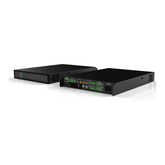
Introduction and Overview 1. Introduction 2. Amplifier Overview THEORY DLC amplifiers are half rack width, 1U format power amplifiers THEORY DLC power amplifiers have been designed to provide that can drive both conventional low impedance (Lo-Z, 4-ohms to 16-ohms) configurable, consistent and reliable high performance audio... -
Page 5: Carton Contents
Introduction and Overview 3. Carton Contents 2.4 Firmware This manual describes the features, functions and user interface of THEORY THEORY DLC amplifiers are shipped in a cardboard carton containing the DLC amplifiers running Firmware Version 1.2.0. amplifier unit, a mains cable appropriate for the sales territory, an accessory pack, and a document pack. - Page 6 DLC-250.4 LOUDSPEAKER CONTROLLER Overview Diagram 1 THEORY DLC four channel amplifier dimensions. (Shaded area defines ventilation space.) 44 mm 80 mm 1.7 in 3.1 in 25 mm 319 mm 1.0 in 12.6 in 220 mm 8.7 in...
-
Page 7: Installation
Note: The rack mounting and desk/wall mounting components described Rack Ear + Half-rack Extension. and illustrated in Sections 4. 1 to 4.3 are not supplied with THEORY DLC Rack Ear + amplifiers but are available to purchase as accessories. Contact your 2 x M4 x 8 amplifier re-seller for more information. -
Page 8: Free-Standing
4.2 Free-standing Adhesive Foot 4 positions If not installed in an equipment rack, THEORY DLC amplifiers can be placed free-standing on a flat surface. Adhesive rubber feet are supplied for this purpose. THEORY DLC amplifiers can also be attached to the underside of desks or wall mounted using connecting plate hardware. -
Page 9: Network Services
Wait for the front panel Network indicator to illuminate green to indicate that the amplifier has network connectivity. 3. The THEORY DLC amplifier default LAN IP address is 192. 1 68.64. 1 00. Configure the laptop or desktop computer for a fixed IP address in the same IP range;... -
Page 10: Configuration Menus
Input Tab. Diagram 5b illustrates 5.3 Configuration Menus the Input Tab. Opening a web browser that is network connected to a THEORY 5.3.2 Zone Tab DLC amplifier initially displays the THEORY DLC Control Web App Dashboard illustrated in Diagram 5a. - Page 11 Note: The number of individual outputs available for configuration Note: Compression can be useful to reduce the volume will depend on the THEORY DLC amplifier model and the input, difference between loud and quiet audio material. The lower the zone and output mode configuration.
- Page 12 DLC-250.4 LOUDSPEAKER CONTROLLER Configuration Diagram 5f The Delay menu enables delay to be applied to individual amplifier • Speaker Preset import file selection outputs. The Equalizer menu enables parametric equalization to be applied • to individual amplifier outputs. Equalizer settings configured for one amplifier output can be copied and applied to other outputs.
- Page 13 DLC-250.4 LOUDSPEAKER CONTROLLER Configuration Diagram 5g Diagram 5h Speaker Preset applied Speaker Preset parameter adjustment 3. If the Speaker Preset data requires modification it can be Note: FIR coefficient files in either .csv or .txt format can be customized by selecting the CUSTOMIZE PRESET option.
- Page 14 DLC-250.4 LOUDSPEAKER CONTROLLER Configuration Note: In automatic mode, the peak limiter parameters adjust automatically in response to Crossover & Gain high-pass filter settings. The Output Mode preset menu enables individual amplifier outputs to • be switched off or configured for Lo-Z or Hi-Z modes. In Hi-Z modes, a high-pass filter can also be configured and applied to the output.
- Page 15 • options and parameters. 5.4 Setup and Signal Routing Thanks to their network based configuration features, THEORY DLC amplifiers offer considerable versatility in terms of sources, signal routing, installation zones and output modes. Inputs can be freely assigned to installation zones, and those zones assigned freely to the available amplifier outputs in either Lo-Z or Hi-Z modes.
- Page 16 • 1 x mono Hi-Z zone + 1 x stereo Lo-Z zone • 1 x mono Hi-Z zone + 2 x mono Lo-Z zones Note: When configured in Hi-Z mode THEORY DLC amplifiers operate in ‘bridged’ mode where the output of two channels is combined.
- Page 17 DLC-250.4 LOUDSPEAKER CONTROLLER Configuration 5.5 GPIO Setup and Connection THEORY DLC amplifiers provide a GPIO socket that enables remote control of volume, standby, mute and trigger functions. The GPIO connector pin functions are described in the GPIO Settings menu illustrated in Diagram 5l. The connection of GPIO based remote volume control and standby/mute are illustrated in Diagram 5m and Diagram 5n respectively.
-
Page 18: Input Connection
RCA Phono socket. The S/PDIF input is connected by default to amplifier installation Zones A (left) and B (right). THEORY DLC amplifiers have no mains power switch and are operational as soon as mains power is connected. Ensure that all signal, GPIO... -
Page 19: Gpio Connections
≈16 6.5 GPIO Connections ≈14 <250 If any THEORY DLC GPIO functionality is required, cables will need ≈12 <250 <250 to be connected to the supplied GPIO connector. Connecting cables to the GPIO connector is illustrated in Diagrams 6d. - Page 20 DLC-250.4 LOUDSPEAKER CONTROLLER Diagram 6b Diagram 6d Balanced analog input GPIO cable connections. cable connections. 5 mm 5 mm Low-Z Mode Diagram 6c Output cable connections. 5 mm Hi-Z Mode 5 mm The exclamation point printed next to the output terminals of the amplifiers is, in addition to the CLASS 2 WIRING text, intended to alert users to the risk of hazardous voltages.
-
Page 21: Operation
7.3 Default Reset menu of the Settings Tab. THEORY DLC amplifiers can be returned to their default settings via either Amplifier outputs will mute if no input signal is present for 5 minutes, and the the Control Web App Settings Tab or the hardware reset pinhole button. The amplifier will switch automatically to Standby Mode if no signal is present reset pinhole button is located on the underside panel of the amplifier. -
Page 22: Specifications
DLC-250.4 LOUDSPEAKER CONTROLLER Specifications Model DLC-250.4 Total System Power 500 W Output Power @ 4/8Ω 4 x 125 W Output Power @ 2 x 250 W 70/100V* Powershare (up to) 2 x 250 W Across all channels** Power Consumption 150W 44 x 220 x 319 mm Dimensions (1.7 x 8.7 x 12.6 in) Weight 2.8kg (6.2 lbs) Output Circuitry UMAC™ Class D - full bandwidth PWM modulator with ultra-low distortion Output Voltage 70Vp / 140Vpp (unloaded) / / Bridged 140Vp / 280 Vpp (unloaded) Signal To Noise-Ratio >106dB (A-weighted, 20Hz-20kHz, 8Ω load) THD+N (typical) < 0.05% (20Hz-20kHz, 8Ω load, 3dB below rated power) Frequency Response 20Hz-20kHz (+0/-0.25dB (8Ω load, 3dB below rated power) Protection Circuits Short circuit -, DC -, Undervoltage -, Temperature - and Overload protection UREC™ universal mains switch mode power supply with Power Factor Correction (PFC)
Need help?
Do you have a question about the DLC-250.4 and is the answer not in the manual?
Questions and answers