Table of Contents
Advertisement
Advertisement
Table of Contents

Related Manuals for veise RZ-A


Summary of Contents for veise RZ-A
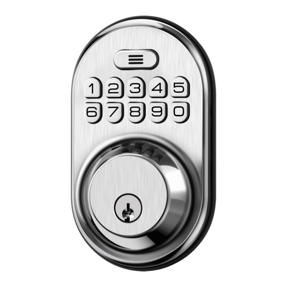
- Page 1 RZ-A Keypad Digital Deadbolt Installation Guide / Programming Instructions Thank you for purchasing our products. Please review this manual thoroughly before operating your device. All pictures in this manual are for illustration purpose only. Actual product may vary due to product upgrade.
-
Page 2: Installation Video
INSTALLATION INSTALLATION Have an issue? VIDEO VIDEO Before you return your product, please contact our customer service team directly. We guarantee a professional service that can solve your issue in a faster, more efficient manner. www.iveise.com Scan to access installation video www.iveise.com/videos support@iveise.com... -
Page 3: Installation Overview
Installation Overview Programming Instructions STEP 1: Prepare the door and check dimensions At a Glance P 15 Factory Default Settings STEP 2: Install the latch and strike How to Use Troubleshooting STEP 3: Install exterior assembly P 11 Definitions STEP 4: Install interior assembly P 12 Code Format STEP 5: Detect left/right hand door installation... - Page 4 Battery INSTALLATION OVERVIEW Cover (G) Interior Assembly (F) Mounting plate (E) Exterior Assembly Mounting plate Screws (J) Latch (A) Interior Assembly Screws (K) Strike (C) Latch Screws Backup key (M) Strike Screws...
-
Page 5: Parts List
Parts List Latch x1 Drive-In Collar (Optional) Strike x1 Exterior Assembly x1 Mounting Plate x1 Interior Assembly x1 Battery Cover x1 Strike Screws x2 Latch Screws x2 Mounting plate Interior Assembly Reset Tool x1 Backup Key x2 Screws x2 Screws x3 If any parts are missing or damaged, please contact Customer Support. - Page 6 STEP Prepare the door and check dimensions 2-3/8" or 2-3/4" (60 or 70mm) Measure to Measure to confirm confirm that the that the backset is hole in the door is either 2-3/8" or 2-1/8" (54mm). 2-3/4" (60 or 70mm) Measure to confirm that the hole in the door edge is 1"...
- Page 7 STEP Install the latch and strike Determine backset and adjust the latch No adjustment is required. Proceed to next step. Slotted hole is NOT centered. Hold the latch in front of the door hole, Rotate and pull the with the latch face flush against the latch as shown to door edge.
- Page 8 Use a screwdriver to test if deadbolt works smoothly. IMPORTANT: Install strike on the door frame. Make sure the hole in door frame is drilled a minimum of 1" (25mm) deep.
-
Page 9: Install Exterior Assembly
STEP Install exterior assembly IMPORTANT: Unlocked Locked Before installation, make sure the latch is fully retracted (in the unlocked position) Keep parallel to door edge. Tourque blade Mounting plate Screws(J) With the latch fully retracted (in the unlocked Secure the mounting plate with the position), route the cable below the latch, and supplied screws. -
Page 10: Install Interior Assembly
STEP Install interior assembly Insert the cable connector to the Push the battery cover out in socket. Push the the direction as illustrated. connector in firmly until it is completely IMPORTANT: attached. Do not load batteries until lock is completely installed. Keep the thumb turn in vertical position and install Attach Interior the interior assembly. - Page 11 STEP Detect left/right hand door installation This step is required and crucial for the lock IMPORTANT: to operate properly. Reset the lock to teach the lock the orientation of the door. While the door is OPEN and Load the 4th battery and keep holding Press and hold the Reset button on UNLOCKED, load 3 AA batteries the interior assembly by using the...
-
Page 12: Programming Instructions
PROGRAMMING INSTRUCTIONS At a Glance Exterior Assembly Interior Assembly Multi-Function Battery Cover Button(MFB) Keypad Reset Button Keyhole Thumb Turn... -
Page 13: How To Use
How to Use UNLOCK the door from inside UNLOCK the door from outside Rotate the thumb turn to Master code + User code + Unlock position. LOCK the door from outside LOCK the door from inside Auto Lock Mode Manual Mode Auto Lock Mode Manual Mode In Auto Lock mode, the bolt... - Page 14 Definitions Programming Basic • Master Code • Silent Mode Required for programming and feature settings. Master code can be The beep sounds when pressing keypad can be muted. But you will used to unlock the door under vacation mode. The default master still hear low battery and system alerts.
-
Page 15: Code Format
Code Format Programming Basic 12345678 1. Master Code(4 to 10 digits): The default Master Code is . It is required that you change it to a code of your own before programming. 2. User Code (4 to 10 digits): A total of 20 User Codes (including one temporary one-time User Code) can be programmed and stored. 3. -
Page 16: Quick Setup
12345678 The default Master Code is IMPORTANT: Quick Set Up It is required that you change it to a code of your own before programming. + Master Code + New Master Code + New Master Code + Change Press Master Code Succeed Wait for long green lights... - Page 17 Auto Lock Enabled + Master Code + Press Green light flash Auto Lock Auto Lock Disabled Green light flash Wait for long green lights Wait for green light flash Enter New Duration Time + Master Code + Press (10-99) Set Auto Lock Time Succeed Wait for long green lights...
-
Page 18: Factory Default Settings
Factory Default Settings How to Reset? Reset button The resetting will delete all User Codes stored IMPORTANT: in the lock. Step 1. Keep the door open and unlocked. Step 2. Press and hold the Reset button, at the same time take out one battery and then place it back. -
Page 19: Troubleshooting
Troubleshooting Why does not the latch extend but the motor is rotating Why does my lock only work properly when the backup key when resetting my lock? is in? Why am I unable to pull the key out in the unlocked position? Improper installation may have caused the issue. -
Page 20: Information & Safety Warnings
Information & Safety Warnings • Protect your User Codes and Master Code. • Care should be taken to ensure a long-lasting finish. When cleaning is required use a soft, damp cloth. Using lacquer thinner, caustic soaps, • Restrict access to your lock’s interior assembly and routinely check your abrasive cleaners or polishes could damage the coating and result in settings to ensure they have not been altered without your knowledge.
Need help?
Do you have a question about the RZ-A and is the answer not in the manual?
Questions and answers
lock will not take a code to add it keeps showing a red light
The Veise RZ-A lock is not accepting a code and showing a red light because either the code or fingerprint entered is incorrect, or the battery is low. A red light flash is used for both situations, but it's not a strong alert for low battery.
This answer is automatically generated
will not program more than one fingerprint