
Related Manuals for Pyle PLXR2B

Summary of Contents for Pyle PLXR2B
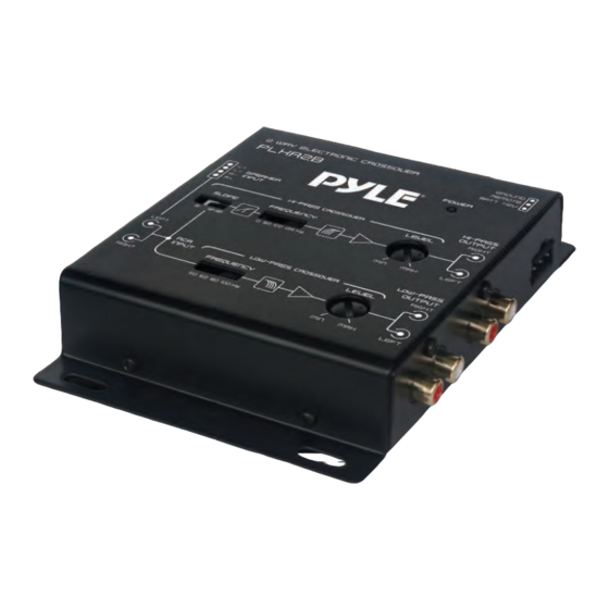
- Page 1 2-Way Electronic Crossover Network Independent High-Pass/Low-Pass Output Level Controls...
-
Page 2: Speci Cations
Speci cations Features: • 2-Way Electronic Crossover • Compact Size • High/Low Impedance Input • Independent High-Pass/Low-Pass Output Level Controls • Special and Better Crossover Slope Design • 4-Channel RCA Outputs • 2 Channel RCA Inputs • Power on LED Indicator What's in the Box: •... - Page 3 FUNCTIONS Control Panel Layout FUNCTIONS 1. POWER INPUT CABLE (12V) To be connected to the positive terminal of your vehicle battery or other constant +12V source. 2. GROUND INPUT CABLE (GND) To be wired to the vehicle's chassis ground. 3. REMOTE TURN-ON INPUT CABLE To be connected to the remote control wire or antenna lead of the source unit for remote ON/OFF.
- Page 4 4. POWER INDICATOR This indicator lights up when the internal switching power supply is activated and the unit is operational. 5. LEFT/RIGHT HIGH IMPEDANCE INPUT To be connected to output of source unit. 6. LEFT/RIGHIT LOW IMPEDANCE INPUT If RCA output is not available, connect speaker outputs of signal source to this input.
-
Page 5: System Diagram
SYSTEM DIAGRAM Remote Turn-On Lead from Head Unit Battery Positive (B+) www.PyleUSA.com... -
Page 6: Installations
INSTALLATIONS CAUTIONS: Please follow all the installation recommendations and instructions in this manual, Installing and for using the electronic crossover in methods other than those outlined herein may reduce the performance capability of the crossover. Any such installation or usage may render the product warranty void. A. - Page 7 C. MOUNTING 1. Place the crossover at the desired location and use it as a template to determine the exact position of the mounting holes. Mark the mounting holes with a pen. 2. Use a center punch to ensure drilling the exact position for the screws. Drill four (4) 1/8 pilot holes.
-
Page 8: Installation
5. Ground Connection Connect the ground input cable of the crossover to the vehicle chassis. For better conductivity. If necessary, scrape paint o the chassis to reveal bare metal at the contact point. 6. Connect the Remote Input Terminal of the crossover to the Source Unit Connect the remote input cable of the crossover to the remote output terminal of the source unit to establish crossover remote power on/o via the source unit. -
Page 9: System Check
System Check A. PRELIMINARY ADJUSTMENT 1. Pre Setting a. Preset high-pass and low-pass ampli er input gain to half of their maximum. b. Preset the crossover frequencies and output levels as follows: High-Pass Frequency Selector: 125 Hz Low-Pass Frequency Selector: 100 Hz High-Pass Output Level: 10 o'clock position Low-Pass Output Level: 10 o'clock position c. -
Page 10: Crossover Frequency Adjustment
B. CROSSOVER FREQUENCY ADJUSTMENT When setting the crossover frequencies, it is best to use compact discs or cassette tapes with greater dynamic range. Usually home recorded tapes are better in this respect than commercially recorded tapes. System Check 1. Center the tone, balance and fader controls of the source unit (leaving the other controls at their previous positions). -
Page 11: Noise Check
D. CROSSOVER FILTER SLOPE SELECTION When the high-pass crossover point is set close to the speaker's frequency response roll-o of 12 dB per octave (even order), by selecting the 6 dB per octave high-pass crossover slope, the combined e ect is the ideal odd order (18 dB) lter type frequency response. -
Page 12: Troubleshooting
TROUBLESHOOTING PROBABLE CAUSE SYMPTOM Check all the ground, B+ and remote cables for tight connection. ● No power Check all fuses. ● Use a Volt/Ohm meter to check all power wire connections to see ● if the system is receiving + 12V. Check if the crossover B+ power input is connected directly to ●... - Page 13 www.PyleUSA.com...
- Page 14 Questions? Issues? We are here to help! Phone: (1) 718-535-1800 Email: support@pyleusa.com...
Need help?
Do you have a question about the PLXR2B and is the answer not in the manual?
Questions and answers