Table of Contents
Advertisement
Quick Links
Advertisement
Table of Contents

Related Manuals for Selec VFD Series


Summary of Contents for Selec VFD Series
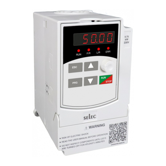
- Page 1 Compact & Powerful VFD Series...
- Page 2 User Manual Preface PREFACE Thank you very much for choosing the VFD-L series high-performance Variable Frequency Drives (VFD). This manual will provide you with the detailed steps and precautions regarding installation, wiring, setting of functional parameters, routine maintenance, malfunction diagnosis and solution etc. The VFD-L series of drives focuses on providing you with the best levels of scalar control of asynchronous AC motors.
-
Page 3: Table Of Contents
User Manual Contents CONTENTS 1. Safety precautions 1.1 Warning 1.2 Safety guidelines 1.3 Delivery and Installation 2. Installation 2.1 Installation environment 2.2 Installation instructions and space limit 3. Wiring 3-1 Connection methods for assorted devices 3-2 Standard Wiring Diagram 3-3 Description of Terminals 3-3-1 Connection of Input Power Terminals 3-3-2 Connection of Output Power Terminals 3-3-3 Earth terminal PE... - Page 4 User Manual Contents P8- Simple PLC and multispeed options P9- Protection Parameters PA- Fault History Pb- Communication parameters PC- Enhanced Parameters 6-2 Detailed Explanation of Functional Parameters- P0- Basic Parameters P1- Keypad Parameters P2- Start and Stop Parameters P3- Motor Parameters P4- Scalar Control Parameters P5- Input Function Parameters P6- Output Function Terminals...
-
Page 5: Safety Precautions
User Manual 1. Safety Precautions Read this manual carefully and follow all safety precautions before moving, installing, operating and servicing the variable-frequency drive (VFD). Ignoring the safety protocols can result in damage or loss of life or property. 1.1 Warning People working on the device should take part in professional electrical and safety training, receive the certification and be familiar with all steps and requirements of installing, commissioning, operating and maintaining the device to avoid any hazards. -
Page 6: Installation
User Manual 2. Installation 2.1 Installation environment The surroundings must be free from dust, caustic/corrosive/inflammable gases/liquids Ÿ There shouldn’t be any metal particulates in the surrounding air Ÿ The ambient temperature should be -10°C ~ +50°C. Sufficient ventilation should be available. Ÿ... -
Page 7: Wiring
User Manual 3.WIRING For the safety of the operator as well as devices, only the professional engineers are allowed to operate it. Please pay attention to the following precautions while wiring. Power must be shut off before wiring. PE earth terminal must be connected with the ground. The rated voltage must conform to AC voltage. -
Page 8: Standard Wiring Diagram
User Manual 3-2 Standard Wiring Diagram Single phase supply source 230V ± 15% Main Circuit Grounding of Power Motor Grounding Measurments Control Circuit Forward Rotation Reverse Rotation Forward Jog External Fault I/P For NPN 485+ For PNP(Default) 485- Potentiometer Input Input 0-10V Multi-functional AI Output of relay... -
Page 9: Description Of Terminals
User Manual 3-3 Description of Terminals Terminal symbol (code) Functional descriptions Terminals for Single-phase AC input 220V Output terminals, connect with three-phase AC electromotor U, V, W Terminal of ground (Earth terminal) For safety's sake, please connect wires according to the regulations of National Electrical Code while proceeding wiring. -
Page 10: Earth Terminal Pe
User Manual 3-3-4 Earth terminal PE For safety's sake, earth terminal PE must be well grounded to reduce noise. Please use the standard ground lead which should be as short and thick as possible (its grounding impedance should be no more than 10Ω). Do not connect its ground lead with that of a high-current loading machine to the ground at the same time, for example, welder or high-power motor, they must be grounded separately. -
Page 11: Keyboard And Panel
User Manual Multi-core shielded cable or stranded wire should be used to connect control terminals. The terminal which is closed to the converter must be connected to earth terminal PE. When wiring, the control cables must be kept away from the main circuit and high-current circuit by at least 30cm. Instead of parallel wiring, vertical wiring should be adopted to prevent the drive from malfunctions resulting from external interference. -
Page 12: Function Leds Descriptions
User Manual 4.3 Function LEDs descriptions Function Denotes that the drive is in RUN operation Denotes the direction of operation of the drive. OFF - Forward ON - Reverse Denotes the source of control for the drive. OFF - Local control using the keypad , ON - Remote control Denotes presence of error condition BLINKING - Pre-alarm condition triggered STEADY - Fault condition triggered... -
Page 13: Illustrations Of Keyboard Operations
User Manual 4.5 Illustrations of keyboard operations... -
Page 14: Running
User Manual 5. RUNNING 5-1 Commissioning 5-1-1 Check before running Please confirm that there is no short circuit between terminals or any exposed charged Ÿ component. Do not connect the unit to the power supply until the enclosure is assembled and closed. Ÿ... -
Page 15: Quick Commissioning
User Manual 5-1-3 Quick Commissioning Start Connection as per wiring diagram Power ON Set Motor Parameters as per nameplate data in P3 group Select Frequency source in P0-01 Select Control mode in P0-02 Set Acc and Dec times in P0-04 and P0-05 Select start and stop modes in P2-00 and P2-05 Check protection levels in... -
Page 16: Specifications Of Functional Parameters
User Manual 6. SPECIFICATIONS OF FUNCTIONAL PARAMETERS 6-1 Functional Parameters Table For ease of programming, the settings have been classified into basic and advanced as mentioned in the table below. “○”: It indicates that the specified parameter can be varied irrespective of the drive’s run-state “●”: It indicates that specified code parameters cannot be changed or modified while the drive is running. -
Page 17: P1- Keypad Parameters
User Manual Basic Fun. Default Modifi- M-bus Description Settings and Range Setting Code Value cation Address 0.0Hz- Upper limiting Frequency Lower limiting P0-10 0.0 Hz 40010 frequency (P0-09) 0.0Hz- Upper limiting Frequency P0-11 Jog Frequency 5.0 Hz 40011 (P0-09) Carrier 1-16 KHz 5KHz P0-12... -
Page 18: P2- Start And Stop Parameters
User Manual P2- START AND STOP PARAMETERS Basic Fun. Default Modifi- M-bus Description Settings and Range Setting Code Address Value cation 0: Direct Start P2-00 Start mode 40200 1: DC Braking Start Starting frequency P2-01 0.0 – 10.0 Hz 0.5 Hz 40201 Retention time P2-02... -
Page 19: P4- Scalar Control Parameters
User Manual P4 – SCALAR CONTROL PARAMETERS Basic Fun. Default Modifi- M-bus Description Settings and Range Setting Code Value cation Address 0: General V/f 1: 1.5 Power V/f V/f curve setting 2: 1.7 Power V/f P4-00 40400 3: 2 Power V/f 4: Multipoint V/f V/F Intermediate 0.0 Hz –... - Page 20 User Manual Basic Fun. M-bus Default Modifi- Description Settings and Range Setting Code Value cation Address P5-06 Lower Limit OF AI2 0.0 – 100.0 % 0.5 % 40506 Corresponding P5-07 Setting of AI2 0.0 – 100.0 % 0.0 % 40507 Lower Limit Upper Limit OF AI2 P5-08...
-
Page 21: P6- Output Function Parameters
User Manual Basic Fun. M-bus Default Modifi- Description Settings and Range Setting Code Value cation Address 0: Two-Wire Control Mode 1 Terminal 1: Two-Wire Control Mode 2 P5-18 40518 Control Mode 2: Three-Wire Control Mode 1 3: Three-Wire Control Mode 2 Terminal P5-19 2 ms- 100 ms... -
Page 22: P8- Simple Plc And Multispeed Options
User Manual Basic Fun. Default Modifi- M-bus Description Settings and Range Setting Code Value cation Address Integral time P7-05 0.0 to 100.0 s 1.0 s 40705 P7-06 Deviation limit 0.0 to 20.0 40706 Sampling Time P7-07 0.1 to 100.0 s 0.2 s 40707 Feedback... -
Page 23: P9- Protection Parameters
User Manual Basic Fun. Default Modifi- M-bus Description Settings and Range Setting Code Value cation Address Sixth phase time P8-14 0.0-999.9 40814 Seventh phase P8-15 0.0-999.9 40815 time Time unit of 0: Seconds; 1: Minutes P8-16 40816 multi-velocity 2: Hours 0-255 BIT0-7 indicates Running direction directions... - Page 24 User Manual Critical value of Under- P9-13 85 % to 99 % 90 % 40913 voltage protection Undervoltage trip time P9-14 0.1 to 999.9 s 0.1 s 40914 Undervoltage pre-alarm 0: Disabled; 1: Enabled P9-15 40915 enable Undervoltage pre-alarm P9-16 P9-13 to 100% 95 % 40916...
-
Page 25: Pa- Fault History
User Manual PA- FAULT HISTORY Basic Settings and Fun. Default Modifi- M-bus Description Range Setting Code Value cation Address PA-00 Previous fault code 0-20 × 41000 2nd to previous fault code PA-01 0-20 × 41001 3rd to previous fault code PA-02 0-20 ×... -
Page 26: Pc- Enhanced Parameters
User Manual PC- ENHANCED PARAMETERS Basic Fun. Default Modifi- M-bus Description Settings and Range Setting Code Value cation Address PC-00 Acc. time 1 0.1 – 999.9 s 20.0 s 41200 PC-01 Dec. time 1 0.1 – 999.9 s 20.0 s 41201 PC-02 Acc. -
Page 27: Detailed Explanation Of Functional Parameters-P0- Basic Parameters
User Manual 6-2 Detailed Explanation of Functional Parameters P0 : Basic parameters 0: Display Only Basic Parameters Parameter 1: Display All Settable Parameters P0-00 Default : 0 setting 2: Disable Parameter Settings mode 3: Factory Reset For ease of use, the entire parameter list has been divided into advanced and basic functions. When the setting is 0, only these basic parameters are visible and available for editing. - Page 28 User Manual Lower limiting Frequency (P0-10) Frequency P0-03 Default : 50.0 Hz setting -Upper limiting Frequency (P0-09) This function reflects the set frequency. When using external communication, this parameter needs to be updated for updating the drive’s set frequency. P0-04 Acc.
- Page 29 User Manual Anti-reversion 0: Disable P0-07 Default : 0 setting 1: Enable This setting determines if the reverse operation will be allowed. If enabled, the drive will only allow operation in the FWD direction as determined through the setting of P0-06. Any attempt to operate the drive in the reverse direction through the keypad, terminals, communication, etc.
-
Page 30: P1- Keypad Parameters
User Manual P1 : Keypad Parameters 0: Setting Frequency 1: Output Frequency 2: Output Current 3: Bus Voltage 4: IGBT Temperature 5: Output Voltage 6: Output Power Default startup display 7: Percentage of Output Current P1-00 Default : 0 8: Count Value parameter 9: PI Index Value 10: PI Feedback Value... -
Page 31: P2- Start And Stop Parameters
User Manual 0: Keypad UP/DOWN keys 1: Keypad Encoder Frequency Switch P1-04 2: AI1 (Pot input) Default : 0 Source 3: AI2 (Analog Input) 4: Communication Reference Lower Limit Frequency to P1-05 Default : 0.0 Hz Frequency Upper Limit Frequency The user is given the option to switch between 2 frequency sources. - Page 32 User Manual Starting Frequency P2-01 0.0 – 10.0 Hz Default : 0.5 Hz Retention time for starting P2-02 0.0 – 50.0 s Default : 0 s Applicable starting frequency can ensure that there is enough torque for starting. Retention time for starting is needed for the formation of magnetic flow while the motor is on standby so that it can start accelerating after the start frequency is stabilized for a certain time.
- Page 33 User Manual Stop signal Time Output Freq. Max Freq. Running Freq. Time Act Dec Time Set Dec Time Ramp to Stop Stop signal Time Output freq. Brake Start freq of DC braking Time Brake time Demagnetizing time DC Brake Assisted Stop This parameter determines how the drive executes the stopping operation 0: In coast to stop, the drive simply turns off all the output switches and the system comes to a halt purely based on the losses incurred due to friction.
- Page 34 User Manual Braking current for P2-07 0 - 150 % Default : 50 % stopping Braking time for P2-08 0.0 – 50.0 s Default : 0.0 s stopping Similar to starting operation, the braking current for stopping is a percentage of the motor rated current and determines the magnitude of the braking current that will be injected into the motor during stopping.
- Page 35 User Manual 0: Running with low Limit Frequency Lower frequency P2-11 1: Stopping Default : 0 limit crossing action 2: Standby 3: Hibernation Hibernation Restore Delay Time 0 – 50.0 s P2-12 Default : 0.0 s Delay Time This setting is used to determine the drive’s operation in cases where the set frequency goes below the lower limiting frequency as set in P0-10.
-
Page 36: P3- Motor Parameters
User Manual P3- Motor Parameters Rated frequency F3 (P4-07) – 400.0 Hz P3-00 Default : 50.0 Hz Default: Depends Rated Voltage Depends on Model P3-01 on Model Default: Depends Depends on Model P3-02 Rated Current on Model Default: Depends Depends on Model P3-03 Rated Power on Model... - Page 37 User Manual V rated Linear 1.5 Power 2.0 Power 1.7 Power Frequency F rated 0: General V/f traces a linear relationship between the output voltage and frequency. It is used generally for constant load applications 1, 2, and 3: The Non-linear curves are usually used in pump and centrifugal applications and help in improving the energy efficiency of the system.
- Page 38 User Manual V rated Freq F rated Torque boost P4-07 0-15.0 % Default : 5.00 % This parameter compensates for output voltage when the converter is running in the low-frequency region, to improve the low-frequency torque which is usually a drawback in scalar control schemes. However, if the setting of torque boost is too high, the motor could overheat or experience an overcurrent condition.
-
Page 39: P5- Input Function Parameters
User Manual 0: Disabled 1: Always Enable P4-08 AVR Function Default : 0 2: Only Enable during deceleration The AVR function ensures that the output voltage of the drive remains stable even in cases where the system might experience fluctuations in the grid voltage. Energy-efficient 0: Disable P4-09... - Page 40 User Manual Corresponding parameter P5-03 P5-01 P5-00 P5-02 P5-06 Lower Limit of AI2 0.0 – 100.0 % Default: 0.5 % Corresponding Setting P5-07 0.0 – 100.0 % Default: 0.0 % of AI2 Lower Limit Upper Limit of AI2 P5-08 AI2 Lower Limit – 100.0 % Default: 0.5 % Corresponding Setting 0.0 –...
- Page 41 User Manual 0: Disable 1: Forward Rotation Multifunction Default: P5-13 2: Reverse Rotation Input X1 3: Three-Wire Control 4: Multiphase Reference Velocity 1 5: Multiphase Reference Velocity 2 6: Multiphase Reference Velocity 3 Multifunction Default: P5-14 7: Forward JOG ; 8: Reverse JOG Input X2 9: Increase Frequency 10: Decrease Frequency...
- Page 42 User Manual Description Function Value Forward Jog Triggers forward jogging operation. Reverse Jog Triggers reverse jogging operation Increase The input terminals are used to increase or decrease the set Frequency frequency value. Decrease The step size is decided by parameter P5-17. The frequency Frequency source (P0-01) has to be set to either 5 or 6.
- Page 43 User Manual 0: Two-Wire Control Mode 1 Terminal Control 1: Two-Wire Control Mode 2 Default: P5-17 Mode 2: Three-Wire Control Mode 1 3: Three-Wire Control Mode 2 This parameter decides the control technique that will be followed when the user selects P0-02 as 1 or 2.
- Page 44 User Manual FWD (RUN) 3W (STOP) REV (DIR) Stop 3: Three-Wire Control Mode 2 FWD (RUN) Forward 3W (STOP) Stop REV (DIR) Reverse Terminal Filtering Default: P5-18 2 ms- 100 ms Time 10 ms This parameter allows the user to customize the debounce time being used for the multifunction input terminals.
-
Page 45: P6- Output Function Terminals
User Manual P6- Output Function Terminals 0: Disable 1: Running 2: Direction 3: Fault Output 4: Pre-Alarm 5: Standby 6: Frequency arrived 7: Frequency detected Relay Output 8: Upper Limit Frequency Default: P6-00 Options 9: Lower Limit Frequency 10: Setting Count Value Received 11: Specified Count Value Received... -
Page 46: P7- Pi Control Parameters
User Manual Description Function Value The output terminal denotes that the internal counter has Specific Count reached the specific count value (P12-16) Value Reached Denotes that the input signal at AI1 has gone below the AI1 Signal Loss user defined threshold value set in parameter P5-05 Threshold Reached Denotes that the input signal at AI2 has gone below the AI2 Signal Loss... - Page 47 User Manual Proportional gain (P) determines the intensity of adjustment of PI regulator; the larger P-value is, the higher the intensity of adjustment will be. Integral time (I) determines the speed of integral regulation on the difference between PI feedback quantity and given quantity.
- Page 48 User Manual Feedback variable Deviation limit Present value Time Output frequency Time Sampling Time P7-07 0.1 to 100.0 s Default: 0.2 s Sampling period (T) means sampling period of feedback quantity; operation is performed by regulator once every one sampling period. The longer sampling period is, the slower response will be. Feedback P7-08 0.1 % to 50.0 %...
-
Page 49: P8- Simple Plc And Multispeed Parameters
User Manual P8 – Simple PLC and Multispeed parameters 0: Disabled 1: Program stops after running for one cycle Program run 2: Program runs for one cycle and P8-00 Default: 0 mode then continues at last operating frequency 3: Circulatory running of the program This parameter selects how the Simple PLC program will run0: Simple PLC operation is disabled. - Page 50 User Manual Frequency (Hz) P8-01 P8-02 P8-03 P8-03 Time (t) P8-08 P8-09 P8-10 P8-11 P8-12 P8-13 P8-14 P8-15 P8-07 P8-04 P8-06 P8-05 Time unit of 0: Seconds ; 1: Minutes P8-16 Default : 0 multivelocity 2: Hours The P8-16 parameter defines the time unit that will be used for the time settings in P8-08 to P8-15 Running direction 0-255 BIT0-7 indicates directions P8-17...
-
Page 51: P9- Protection Parameters
User Manual Acc-Dec Time for 0-65535 BIT0-15 indicated P8-18 Default: 0.0 each phase acc/dec times for 0-7 Weighted value Time selection (example) Bit No. 11 10 Phase No. The P8-18 parameter determines the acceleration or deceleration times that will be followed for the individual phases in the simple PLC program. - Page 52 User Manual The Overload protection is used to provide a degree of thermal protection to the motor. The pre- alarm feature can be used to highlight that the system is approaching the critical trip state so that corrective actions can be taken accordingly. The percentage values specified in the parameters P9- 01 and P9-04 correspond to the percentage of the rated power of the motor as specified in the parameter P3-03.
- Page 53 User Manual Overcurrent 0: Disabled P9-18 Default : 1 protection enable 1: Enabled Critical value of Default : P9-19 100 to 180 % Overcurrent protection 120 % Default : Overcurrent trip 0.1 to 999.9 s P9-20 time 0.1 s Overcurrent prealarm 0: Disabled P9-21 Default : 0...
-
Page 54: Pa- Fault History
User Manual PA- Fault History The fault history section helps in analysing the faults faced by the drive. PA-00 0-20 Previous fault code 2 to previous fault code PA-01 0-20 3 to previous fault code PA-02 0-20 These addresses store the fault codes of the previous 3 faults faced by the drive. A summary of the fault codes can be found in Appendix A which deals with fault handling and troubleshooting. -
Page 55: Pc- Enhanced Parameters
User Manual The above parameters deal with the external communication feature of the drive. The parameter P11-00 defines the slave ID that will be assigned to the VFD. Note that the drive always acts as a slave in the communication system. The parameter P11-01 defines the baud rate at which the communication system will operate. - Page 56 User Manual Hopping action is required in cases where the VFD could drive the motor through a frequency that matches the resonant frequency of the system that is being controlled. This matching could cause the entire system to vibrate which could prove to be harmful in the long run. The hopping feature allows the user to skip through such resonant frequency values.
- Page 57 User Manual Lower Limiting Frequency (P0-10) Amplitude of Default: – Upper Limiting Frequency PC-14 Frequency Arrival 0.0 Hz (P0-09) This parameter indicates that the drive is approaching the set frequency value. Output frequency Setting frequency Detected amplitude Time Signal of frequency Time Setting Count PC-15...
-
Page 58: Fault Handling And Troubleshooting
User Manual 7. FAULT HANDLING AND TROUBLESHOOTING 7.1 Malfunction and solutions Fault Fault Fault Indi- Possible causes Possible solutions description Code cation 1. Check input voltage is in 1. Input voltage permissible range 2. Rapid deceleration Overvoltage 2. Increase deceleration time 3. -
Page 59: Common Faults And Processing Schemes
User Manual Fault Fault Fault Indi- Possible causes Possible solutions description Code cation 1. Crosscheck the communication settings across all devices External 1. Erronous comm- communication wires connected to Comm- unication settings the network. unication 2. Damaged 2. Check the status of the wires/ failure cable used for communications 1. -
Page 60: Maintenance
User Manual 8. MAINTENANCE Only the qualified engineer is allowed to conduct maintenance for converter; please pay attention to the following precautions: Maintenance must be conducted only by qualified engineers in specified way Ÿ Only when converter is shut down for 5 minutes can maintenance be conducted Ÿ... -
Page 61: Storage
User Manual 8.3. Storage This product can't be taken out from box until it's about to be installed. To ensure that it's still valid for warranty and available for maintenance in the future during the period of storage, please pay attention to the following points: Relative humidity must be within the range between 0% and 95%;... -
Page 62: External Communication
User Manual 9. EXTERNAL COMMUNICATION The drive features external communication on the form of MODBUS RTU over RS485 interface, which is compliant with International Communication Standards. Centralized control can be implemented by PC/PLC as well as superior controller to adapt specific requirements for applications, including setting of control command, operating frequency, modification of parameters for relevant function code, monitoring of operating status or malfunction. -
Page 63: Frame Structure
User Manual 9.3. Frame Structure In the RTU mode, the format of each byte is as follow: encoding system -8-bit binary system, there are two hexadecimal characters included in every 8-bit frame (hexadecimal characters include 0~9 & A~F). The transmission of new frame will always be restarted with a interval of 3.5 bytes transmission time. -
Page 64: Command Code And Data Description
User Manual 9.4 Command code and data description 9.4.1 Format of No.1 address for Setting as follows, setting frequency 50Hz (P0-03) Host command Slave Response 3.5 byte interval 3.5 byte interval Frame header Frame header Slave address 0x01 Slave address 0x01 Function code 0x06... - Page 65 User Manual 9.4.4 CRC Mode RTU frame format is mainly applied to CRC (Cyclical Redundancy Check), error detecting field based on CRC is included in the message. CRC domain can detect all the information of message, which is two bytes with 16-bit binary value included. It will be added into the message after the calculation of transmission devices.
-
Page 66: Read-Write Rules Of Parameter Address For Function Code
User Manual 9.5 Read-write rules of parameter address for function code 9.5.1 Monitoring Parameters Address Parameter Set Frequency 30000 Output Frequency 30001 Carrier Frequency 30002 Output current 30003 Output voltage 30004 Bus voltage 30005 30006 Motor's RPM 30007 %Full load current IGBT temperature 30008 %Output power... -
Page 67: Appendix
User Manual 10. APPENDIX 10.1 Technical Specifications Rated input voltage/ frequency Single Phase 230 VAC 50 Hz/ 60 Hz Power Permissible voltage fluctuation 230 V ±15 % for Single Phase supply Permissible frequency fluctuation ±5 % Space Vector PWM Based Scalar Control Control mode Frequency Control range 0.1 ~ 400 Hz... -
Page 68: Product Dimensions
User Manual Over Current, Over Voltage, Under Voltage, Over- Protection Functions Temperature, Overload, Under Current, System Error Display parameters Parameters setting, Running status and Fault display Display HMI with 5 keys, Potentiometer 4 x 7 segment with Display Type 4 LED display External MODBUS RTU over RS485 with a maximum baud Protocol... - Page 69 User Manual (Keypad dimension) 89mm 141mm 152mm 123mm 80.5mm Pore Mounting Dimension Dimension Diameter Weight Product Code (kg) length wide length wide height (mm) (mm) (mm) (mm) (mm) (mm) VFD-L-1-005-230 V f4.6 80.5 VFD-L-1-010-230 V...
Need help?
Do you have a question about the VFD Series and is the answer not in the manual?
Questions and answers