Advertisement
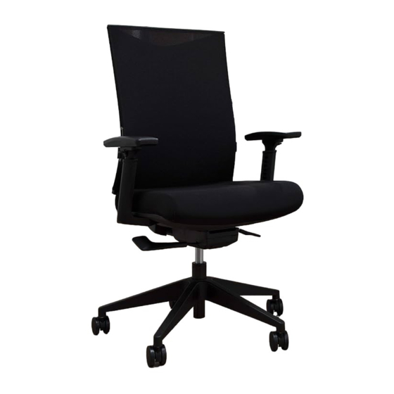
BSX170
1/4" ×1-3/4" Screws
6 Units
1/4" ×1-7/8" Screws
1/4" ×2-1/4" Screws
2 Units
2 Units
5/16" ×7/8" Screws
5/16" ×1-1/8" Screws
2 Units
1 Units
M
N
Φ14mm×Φ6.5 mm×1mm Washer
Allen Wrench
6 Units
1 Units
N
I
J
F
Step 1: Insert Casters (A) into Chair Base (B). Insert Gas Lift (C) into the hole in the center
of the Chair Base (B).
Step 2: Attach Chair Arms (G) to Chair Seat (D) using six 1/4"x1-3/4" Screws (H) and
six Φ14mm×Φ6.5 mm×1mm Washers (M) as shown. Tighten with Allen Wrench (N).
Step 3: Attach Mechanism (F) to Chair Seat (D) using two 1/4"x1-7/8" Screws (I) for front
holes and two 1/4"x2-1/4" Screws (J) for rear holes as shown. Tighten with Allen
Wrench (N).
Step 4: Attach Chair Back (E) to Mechanism (F) using one 5/16"x1-1/8" Screw (L) and
two 5/16"x7/8" Screws (K). Tighten with Allen Wrench (N).
Step 5: Carefully place the assembled Chair Frame onto the Gas Lift (C). Aligning the hole
in the Mechanism on the Chair Seat (D) with the Gas Lift (C). Press down on the
Chair Seat (D) to secure in place.
C
B
N
L
K
E
A
N
HONBASYX.COM
N
H
M
G
D
Advertisement
Table of Contents

Related Manuals for BASYX BSX170

Summary of Contents for BASYX BSX170
- Page 1 BSX170 Step 1: Insert Casters (A) into Chair Base (B). Insert Gas Lift (C) into the hole in the center of the Chair Base (B). Step 2: Attach Chair Arms (G) to Chair Seat (D) using six 1/4"x1-3/4" Screws (H) and six Φ14mm×Φ6.5 mm×1mm Washers (M) as shown.
- Page 2 CONTROL INSTRUCTIONS INSTRUCCIONES DEL CONTROL INSTRUCTIONS DE RÉGLAGE BSX170 LUMBAR SUPPORT ADJUSTMENT Slide the lumbar support up or down to the desired location. RÉGLAGE DU SUPPORT LOMBAIRE Glisser le support lombaire vers le haut ou vers le bas jusqu'à la position désirée.
Need help?
Do you have a question about the BSX170 and is the answer not in the manual?
Questions and answers