
Related Manuals for Vericom VC5 Series

Summary of Contents for Vericom VC5 Series
- Page 1 OWNER’S MANUAL ENGLISH Server / Network Cabinet Installation / Mounting Instructions VC5 Model Series v e r i c o m s o l u t i o n s . c o m — + 1 ( 8 6 5 ) 6 7 1 - 4 4 5 5...
- Page 2 Vericom Global Solutions Legal Disclaimer While every precaution has been taken to ensure the accuracy and completeness of this document, Vericom assumes no responsibility and disclaims all liability for damages resulting from use of this information or for any technical or editorial errors or omissions contained herein.
-
Page 3: Table Of Contents
Table of Contents Safety I nformation ........................1 Introduction ..........................2-5 ....................Introduction to the VC5 Series ..........................Item List ......................Component Identification ........................Included Hardware .......................... Tools Required ... -
Page 4: Safety I Nformation
IMPORTANT SAFETY INFORMATION Save These Instructions This manual contains important safety information and instructions that should be followed during the installation and use of this product. Read and follow all safety, installation, and operating instructions contained in this manual to maintain compliance with agency listings. -
Page 5: Introduction
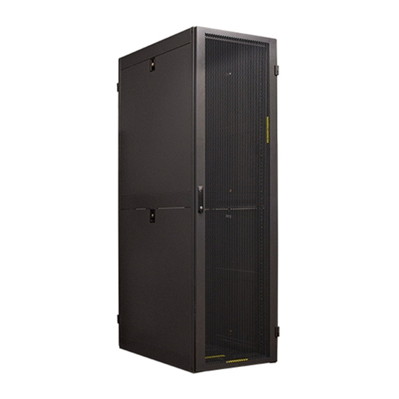
INTRODUCTION Vericom VC5 Series Data, Network, and Server Cabinets are robust, high-quality solutions for storing a wide variety of standard EIA-310 19” rack mount equipment. Available in several height/width/depth combinations, VC5 cabinets provide the versatility and flexibility to meet the needs of today’s demanding applications. And with an expansive list of available accessories, VC5 cabinets can be further customized for specific installations. - Page 6 VC5-7042- x¹x²x³x⁴x⁵ 42U x 29.5” (750mm) W x 39.4” (1000mm) D Data Cabinet VC5-7045- x¹x²x³x⁴x⁵ 45U x 29.5” (750mm) W x 39.4” (1000mm) D Data Cabinet VC5-7047- x¹x²x³x⁴x⁵ 47U x 29.5” (750mm) W x 39.4” (1000mm) D Data Cabinet VC5-7048- x¹x²x³x⁴x⁵ 48U x 29.5”...
- Page 7 VC5-8242- x¹x²x³x⁴x⁵ 42U x 31.5” (800mm) W x 48” (1200mm) D Network Cabinet * VC5-8245- x¹x²x³x⁴x⁵ 45U x 31.5” (800mm) W x 48” (1200mm) D Network Cabinet * VC5-8247- x¹x²x³x⁴x⁵ 47U x 31.5” (800mm) W x 48” (1200mm) D Network Cabinet VC5-8248- x¹x²x³x⁴x⁵...
-
Page 8: Component Identification
Cabinet frame Rear door Bottom panel Mounting rails (4) Side panels (4) Zero-U PDU lacing panels (2) Front door Top panel Casters and levelers Included Hardware Tools Required • (50) 10-32 screws • Utility knife • (50) cage nuts • Phillips screwdriver and/or power drill with Phillips bit • ... -
Page 9: Installation
NOTE: Upon receipt and before moving or unpacking the cabinet, inspect the packaging for signs of damage or mishandling during shipment. If any is found, notify the carrier immediately and contact your distributor or Vericom representative. 1. Before removing any packaging, use a forklift or pallet jack to move the cabinet on its pallet as close to the final installation location as possible. -
Page 10: Moving And Placement
7. Next, use a 10mm socket, box wrench, or a Phillips screwdriver to remove the bolts that secure the Mounting Bracket to the cabinet. NOTE: Do not throw away the Mounting Brackets or the 10mm bolts – they are used to anchor the cabinet to the floor. 8. - Page 11 3. Move the cabinet into the desired installation position. Refer to the chart below to ensure proper clearance around all sides for installation and maintenance of installed equipment. 4. If ganging cabinets together, remove round plastic caps from sides that will be ganged (4 per side). CABINET CABINET WIDTH...
-
Page 12: Leveling
Leveling REMINDER: This cabinet must be installed on a flat, level, structurally sound surface that is able to bear the weight of the cabinet and all the installed equipment, as well as neighboring cabinets and their equipment. 1. Using a 19mm open end wrench or crescent wrench, lower all four levelers until they come in firm contact with the floor. -
Page 13: Anchoring / Floor Mounting
Anchoring / Floor Mounting All VC5 cabinets should be anchored to the floor to ensure proper safety. Failure to do so can lead to serious injury and/or damage to your equipment. 1. To anchor the cabinet to the floor, reuse the mounting brackets that secured the cabinet to the pallet. 2. -
Page 14: Ganging Multiple Cabinets
Ganging WARNING: Ganging of cabinets provides limited stability and is not a substitute for proper leveling and anchoring to the floor. NOTE: Item # RAGAN04 Ganging Kit is required to gang two cabinets together (sold separately). 1. Cabinets can be ganged together with or without side panels installed. 2. -
Page 15: Grounding
Grounding WARNING: Electrical Shock Hazard Each cabinet must be connected to the Common Bonding Network (CBN) separately – do not daisy-chain. Do not use the cabinet without an earth ground connection. 1. There are four 16mm cable entry holes in the bottom of the cabinet frame (one in each corner). Select the location that is most appropriate for your installation, remove the plastic plug, and route the ground wire (not included) up through the hole from below the cabinet. -
Page 16: Configuration
CONFIGURATION The VC5 Series Cabinet is designed for flexibility and can be configured to meet a wide variety of application requirements. Removing and Installing Doors 1. Open the door a minimum of 90°. 2. Disconnect the door’s ground wire. 3. Lift the door off the hinges and move it away from the cabinet. -
Page 17: Removing And Installing Side Panels
Removing and Installing Side Panels VC5 Series Cabinets include (4) side panels that are easily removable. 1. Use the key to unlock the side panel. 2. Disconnect the panel’s ground wire. 3. Lift up on the lock latch and tilt the panel away from the cabinet. -
Page 18: Removing And Installing Bottom Panel
Removing and Installing the Bottom Panel The standard configuration of the VC5 Series Cabinet includes a bottom panel consisting of three or four center panels (depending on the depth of the cabinet) and two side panels that run the entire depth of the cabinet. Each center panel can be removed individually, or the entire bottom can be removed. -
Page 19: Adjusting Mounting Rail Position
Adjusting Mounting Rail Position VC5 Series Cabinets include two sets of preinstalled mounting rails that can be infinitely adjusted front to back. WARNING: Do not attempt to adjust rail position with equipment installed. NOTE: Each rail must remain perpendicular to the cross members of the side frame after adjustment. In addition, both front rails must be the same distance from the front of the cabinet, and both rear rails must be the same distance from the rear of the cabinet. - Page 20 29.5” (750mm) and 31.5” (800mm) wide cabinets: 1. Remove the M5 screws at the top and bottom of the mounting rail. 2. Remove the two M5 screws from the top edge of the rail extension bracket. 3. Slide the mounting rail into the desired position. Measure the distance from the rail to the outside of the cabinet frame at the top and bottom of the rail to ensure perpendicular positioning.
- Page 21 CABINET DEPTH 31.5 in. (800 mm) 2.5 in. (64 mm) 19.5 in. (495 mm) 19.5 in. (495 mm) 24.5 in. (623 mm) 27.0 in. (686 mm) 35.4 in. (900 mm) 2.5 in. (64 mm) 23.5 in. (597 mm) 23.5 in. (597 mm) 28.5 in.
-
Page 22: Equipment Installation
EQUIPMENT INSTALLATION WARNING • This cabinet can easily tip. Do not install equipment until you have anchored the cabinet to the floor. • Install heavier equipment first and toward the bottom of the cabinet to prevent it from becoming top-heavy. • ... - Page 23 This cabinet includes a pack of 50 cage nuts and 50 corresponding 10-32 screws. Should you need additional quantities, please contact your distributor or Vericom representative WARNING: Install cage nuts horizontally with the flanges engaging the sides of the square hole. Never install them vertically.
-
Page 24: Specifications
SPECIFICATIONS Maximum Load Capacity: 3,000 lbs. (1360 kgs) For detailed dimensions refer to VC5 specification drawings. Height Height Depth Depth MODEL Width (frame only) (with casters) (with doors) (frame only) 78.66 in. 80.96 in. 23.62 in. 31.50 in. 29.54 in. VC5-6842- xxxxx (1998.0 mm) (2056.5 mm) - Page 25 Height Height Depth Depth MODEL Width (frame only) (with casters) (with doors) (frame only) 96.17 in. 98.47 in. 23.62 in. 43.3 in. 41.34 in. VC5-6152- xxxxx (2442.7 mm) (2501.1 mm) (600 mm) (1100 mm) (1050 mm) 47.16 in. 49.46 in. 23.62 in.
- Page 26 Height Height Depth Depth MODEL Width (frame only) (with casters) (with doors) (frame only) 78.66 in. 80.96 in. 29.53 in. 43.3 in. 41.34 in. VC5-7142- xxxxx (1998.0 mm) (2056.5 mm) (750 mm) (1100 mm) (1050 mm) 83.94 in. 86.24 in. 29.53 in.
- Page 27 (1150 mm) 96.17 in. 98.47 in. 31.50 in. 47.24 in. 45.28 in. VC5-8252- xxxxx (2442.7 mm) (2501.1 mm) (800 mm) (1200 mm) (1150 mm) NOTE: Not all models are available in all regions. Please contact your Vericom representative for additional information.
-
Page 28: Optional Accessories
OPTIONAL ACCESSORIES Vericom offers a wide variety of accessories to further customize the VC5 Cabinet Series and expand its capabilities. Contact your distributor or Vericom representative for additional information and availability. CABLE MANAGEMENT Lacing Panel Kit w/Plastic Rings, 42U Steel Ring Cable Manager, 1U... -
Page 29: Hardware & Mounting
HARDWARE & MOUNTING RAS3250 10-32 Mounting Screws, 50 pcs RACAL25 2.5" Locking Caster, 2 pack RAS2450 12-24 Mounting Screws, 50 pcs RAKEY01 Extra Cabinet Keys RASM650 M6 Mounting Screws, 50 pcs FB42TH Rails 10-32 tapped 4pc set 42U RAC3250 10-32 Cage Nuts, 50 pcs FB45TH Rails 10-32 tapped 4pc set 45U RAC2450... -
Page 30: Other Miscellaneous Accessories
Vericom Global Solutions 5-Year Limited Warranty Vericom warrants this product, if used in accordance with all applicable instructions, to be free from original defects in material and work- manship for a period of 5 years from the date of initial purchase. If the product should prove defective in material or workmanship with that period, Vericom will repair or replace the product, in its sole discretion.
Need help?
Do you have a question about the VC5 Series and is the answer not in the manual?
Questions and answers