Advertisement
Available languages
Available languages
Quick Links
WARNING
Do not use the device
without referring to this
manual first.
TECHNICAL MANUAL
AGILITY PLUS
CONTROL BOARD
Made by: Motoppar Indústria e Comércio de Automatizadores Ltda
Av. Dr. Labieno da Costa Machado, 3526 - Distrito Industrial - Garça - SP - CEP 17406-200 - Brasil
CNPJ: 52.605.821/0001-55
www.ppa.com.br | +55 14 3407 1000
P06623 - 01/2022
Rev. 3
MAIN FEATURES
• Full Range AC Power Supply (100 – 240V)
• Analog Limit Switch System
• RF receiver on-board
• EEProm Memory for storing both added encrypted remote controls and the control
board setup
• Setup by TACTLED technology
• Up to 256 remote controls
• Option to erase remote controls individually
• Electronic clutch (strength) adjustment
• Automatic acquiring (O/C path)
• Input ports for photocell, pushbutton, and loose receiver
• Output ports for electric lock and courtesy light modules
• Brake adjustment
• Independent adjustment of the limit switch ramp (opening and closing)
• Preset opening delay when a traffic light (Visual exit annunciator) is used
• Compatible with PROG
• 'Pedestrian' function
• 'Alarm' function
• Photocell (NO, NC and Pulse)
• Electronic padlock to lock all added remote controls
• Opening / closing cycles counter
• Temporary blocking and unblocking of individual remote controls.
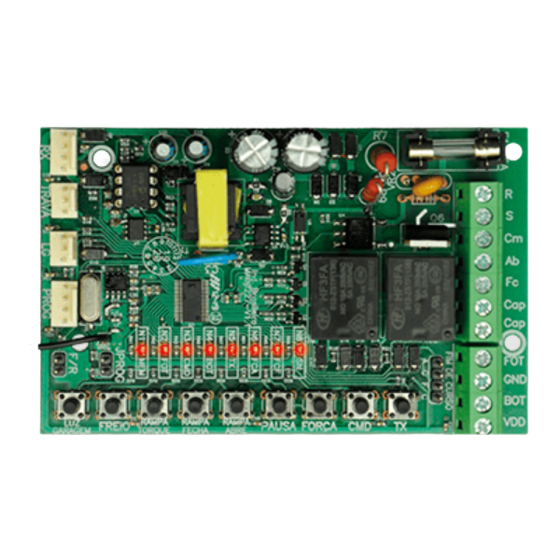
CHART: LED INDICATIONS
Guide for the functions of the
indicator LEDs on the board, when
it is not in programming mode, i.e.,
'JPROG' jumper open.
LED
FUNCTION
• Lit: Empty memory, with no remote controls added.
• Blinking: No memory or faulty memory. In this case, the control board enters the
MEM (N1)
basic operation mode; it means that functions such as external PROG, the program-
ming buttons and the remote controls get disabled. *
FOT (N2)
• Lit: Photocell triggered.
CMD (N3)
• Lit: External receiver or 'CMD' button activated.
BOT (N4)
• Lit: External pushbutton activated.
TX (N5)
• Lit: Added remote control detected.
FCA (N6)
• Lit: Open limit switch triggered.
FCF (N7)
• Lit: Closed limit switch triggered.
SN (N8)
• Blinks every two seconds: Normal operation.
*BASIC OPERATION MODE
Command only enabled by using an external pushbutton, 'CMD' button or external RF
receiver; command during opening maneuver enabled, clutch on the maximum level;
semi-automatic mode; ramps disabled; command for closing during the time pause; CLS
and OLS (CLS = Closing Limit Switch / OLS = Opening Limit Switch) sensors Normally
open and photocell normally open.
- Access buttons
- Button #1, Button #2, Button #3, or Button #4
- Setting the time for triggering the panic alarm [30 sec. up to 10 min.]
- Enable / Disable silent mode of the panic alarm
- Wi-Fi only
- Siren only
- Wi-Fi + Siren
- Panic key action
- Pulse = Secure Access Only
- Pulse = Turn Siren On/Off and Time 3 sec. = Secure Access
- Pulse = Secure Access and Time 3 sec. = Turn Siren On/Off
- Monitoring and Resetting of the panic functions.
• Communication interface with the 'Contatto Wi-Fi Connect' device
• Settings through PROG
• Verification of the operating conditions of the alarm, zones, and panic through the
PROG display
NOTES:
1) The 'Alarm' function is available from version 11.13 of the Agility control board on. If the version
is older and you need to use this function, look for a nearest PPA distributor to update the
firmware.
2) When the gate is closed and the control board receives a signal from a remote control whose
button has a panic function, it will simultaneously trigger the panic timer and the gate to open,
starting the 'Safe Access' cycle. It is important to have in mind that the user-defined panic delay
time must be longer than the time to complete the gate opening/closing cycle, otherwise it will
trigger the panic signal before completing its closing cycle.
3) The control board acknowledges (recognizes) and treats the remote control's panic button as
Pulse when this button is pressed and released between 0.5 and 3 sec.
4) The control board recognizes and treats the control panic button as a 3-second time when this
button is pressed and held on the control above the 3-second time.
5) To set the parameters of the 'Alarm' function, the gate must be open.
6) For more information regarding the 'Alarm' function, consult the manual available on the
website.
CHART: SETTING THROUGH 'PROG' (PROGRAMMING TOOL)
PROG: It allows one to set the control unit in a more precise manner.
While the PROG is connected to the control unit, pushbuttons, the 'CMD' button and
loose receivers will be inoperative for motor activation commands on the control board.
Only by using PROG one can send open / close commands to the gate, by pressing the
'+' button. One can also use an added remote control if it is on the main screen of status
of sensors.
By keeping any button of the PROG pressed, after 3 seconds, it will enter the self-
repetition mode of the pressed button, which will provide you with more agility to
navigate between the screens or adjustments.
FUNCTION
PARAMETERS
Monitors the sensors and the peripherals of the board (OLS, CLS,
TELA INICIAL (HOME
pushbutton, photocell, remote control, Status of the board and
SCREEN)
timers (Courtesy light, Pause and Electromagnetic lock))
Add new remote controls to the board. To add a remote control,
just press its button; 'Transmissor' (Remote Control) will appear
on the PROG (+); press the '+' button. Example:
• 'GRAVAR TX [005]' (ADD TX [005]) -> Total number of added
remote controls
GRAVAR
• 'REGISTRADO [003]' (ADDED [003]) -> Remote control #3 has
TRANSMISSORES
been added, or
(ADDING REMOTE
• 'Já Cadastrado [003]' (Already added [003]) -> Remote control
CONTROLS)
#3 already added
• IDENTIFICAR
TRANSMISSOR
PERDIDO
(IDENTIFY
TRANSMITTER) (Just perform the procedure to add a control
remote with the TX that has been found and the position of
this control will immediately appear on the prog, making the
identification of its respective owner easier).
TEMPO PAUSA
• Semi-automatic
(PAUSE TIME)
• Time for automatic closing (0 second -> 240 seconds)
• 9 Levels
RAMPA
• Off
FECHAMENTO
• 5% Minimum
(CLOSING RAMP)
• 40% Maximum
TORQUE RAMPA FC
• 9 Levels
(CLOSING RAMP
• 20Hz (Minimum)
TORQUE)
• TP10:5 (Maximum)
• 9 Levels
RAMPA ABERTURA
• Off
(OPENING RAMP)
• 5% Minimum
• 40% Maximum
TORQUE RAMPA AB
• 9 Levels
(OPENING RAMP
• 20Hz (Minimum)
TORQUE)
• TP10:5 (Maximum)
• 9 Levels
FORÇA (STRENGTH)
• 0 (Minimum)
• 8 (Maximum)
TEMPO LUZ
GARAGEM
0 second -> 240 seconds
(COURTESY LIGHT
TIME)
COMANDO
ABERTURA
• 'Sim' (Yes – Enabled)
(COMMAND
• 'Não' (No – Disabled)
RECEIVED
WHEN OPENING)
• 9 Levels
FREIO (BRAKE)
• OFF (Disabled)
• 500 ms. (Maximum)
EXCLUIR TX (ERASE
REMOTE
Erases (deletes) all remote controls added to the board
CONTROLS)
To individually erase a remote control (TX), it is necessary
to select the position of the control one wants to erase. After
EXCLUIR TX INDIV
choosing the remote control, the time starts decreasing in 10
(INDIVIDUALLY
seconds, until it reaches 0 second. 'Sim' (Yes) will appear in the
ERASE A REMOTE
Prog: (+) display, together with the selected remote control. Just
CONTROL)
press the '+' button and the
control will be individually erased.
CADEADO TX INDIV
Individually blocks (and unblocks) any chosen registered remote
(INDIVIDUAL TX
control for as long as necessary
LOCK)
Communication protocol:
TRANSMISSOR
• Rolling code (PPA)
(REMOTE CONTROL)
• Fixed code
CHART: COMMAND SETTINGS
Quick configuration guide. To
enter programming mode,
one must close the 'JPROG'
jumper on the board.
BUTTON
FUNCTION
GRV
Add or erase remote controls
CMD
Command received when opening
FORÇA
Strength (Electronic clutch)
PAUSA
Automatic closing time
RAMPAB ABRE
Opening ramp
RAMPFC FECHA
Closing ramp
RAMPTORQ
Ramp Torque (Strength)
TORQUE
FREIO
Brake
LG GARAGEM
Courtesy light time
ERASING ALL REMOTE CONTROLS
Erases and boots the memory to add new remote controls.
Instructions:
1. The gate must be still
2. Close the 'JPROG' jumper
3. Press and release the ' GRV ' button on the control board (once)
4. 'N5' (TX) LED must remain lit
5. Press the 'GRV' button on the control board and keep it pressed for 10 seconds
6. 'N8' LED must remain lit, indicating that all remote controls have been erased from
the memory
7. To finish, open the 'JPROG' jumper.
ADDING REMOTE CONTROLS
It adds new remote controls to the control board, so that they can trigger it.
Instructions:
1. The gate must be still
2. Close the 'JPROG' jumper
3. Press and release the ' GRV ' button on the control board (once)
4. 'N5' (TX) LED must remain lit
5. Press the button of the remote control one wants to add and keep it pressed
6. 'N8' LED must remain blinking
7. Press and release the 'GRV' button on the board to confirm the operation
8. 'N8' LED blinks once (button already added), blinks twice (button already added and
new synchronization for a Rolling Code Remote control) or three times (memory full)
9. Release the button of the remote control
10. Go back to step 3 to add a new button of the remote control
11. To finish, open the 'JPROG' jumper.
COMMAND RECEIVED DURING OPENING
Permission for a command from either a push button or a remote control to be accepted
during the opening maneuver.
Instructions:
1. The gate must be still
2. Close the 'JPROG' jumper
3. Press and release the 'CMD' button on the board (once) to show the current adjustment
4. Press and release the 'CMD' button as many times as necessary until one reaches the
desired adjustment
5. To finish, open the 'JPROG' jumper.
LED indications:
• 'N1' blinking = Function disabled.
• 'N1' lit = Function enabled.
STRENGTH (ELECTRONIC CLUTCH)
To assure the efficiency of this security sensor device, proceed as follows:
- After properly installing the gate opener, adjust the electronic clutch so that the strength
necessary to a complete gate maneuver is minimum when the device is both opening
and closing.
Instructions:
1. The gate must be still
2. Close the 'JPROG' jumper
3. Press and release the 'FORÇA' (STRENGTH) button on the board (once) to show the
current adjustment
4. Press and release the 'FORÇA' (STRENGTH) button as many times as necessary until
one reaches the desired adjustment
5. To finish, open the 'JPROG' jumper.
LED indications:
• 'N1' blinking = Off.
• 'N1' lit = Minimum.
...
• 'N8' lit = Maximum.
SEMI-AUTOMATIC / AUTOMATIC MODE (PAUSE TIME)
It is the time adjustment for the automatic closing when the gate reaches the 'FCA' (OLS)
limit switch sensor or the opening stop, indicating the limit of the opening maneuver.
Instructions:
1. The gate must be still
2. Close the 'JPROG' jumper
3. Press and release the 'PAUSA'(PAUSE TIME) button on the board (once) to show the
current adjustment
4. Press and release the 'PAUSA'(PAUSE TIME) button as many times as necessary until
one reaches the desired adjustment
5. To finish, open the 'JPROG' jumper.
LED indications:
• 'N1 blinking = Semi-automatic.
• 'N1' lit = 5 sec.
• 'N2' lit = 10 sec.
• 'N3' lit = 30 sec.
• 'N4' lit = 60 sec.
• 'N5' lit = 90 sec.
• 'N6' lit = 120 sec.
• 'N7' lit = 180 sec.
• 'N8' lit = 240 sec.
PADRÃO DE
FÁBRICA
Restores all settings to the default factory settings.
(DEFAULT FACTORY
SETTINGS)
Selects the programming tool (PROG) language:
IDIOMA (LANGUAGE
• Portuguese
SELECTION)
• English
• Spanish
RETARDO ABERTURA
(OPENING DELAY
Gate leaf delay time. Time: 0 second -> 15 seconds.
TIME)
Command action during pause time:
• 'Recarga' (Recharge): In this mode, if a command is generated
COMANDO PAUSA
during the closing temporization, the board interrupts the
(COMMAND
counting and restarts the set counting for closing.
ACTION DURING
• 'Fechamento' (Closing): In this mode, if a command is generated
THE PAUSE TIME)
during the closing temporization, the board interrupts the
counting and automatically starts the closing maneuver after
the command has been received.
SENSOR FIM DE
Contact of the Limit switch sensor:
CURSO (LIMIT
• NA (NO – normally open)
SWITCH SENSOR)
• NF (NC – normally closed)
Contact of the Photocell:
CONTATO FOTO
• NA (NO – normally open)
(PHOTOCELL
• NF (NC – normally closed)
CONTACT)
• Pulse (Pulsing)
To erase the path memorized by the control board, it is necessary
PERCURSO /
to perform the 'Erase path' operation, in the following opening
POSIÇÃO
or closing command. The control board will automatically
FIM DE CURSO
memorize a new path after the first complete cycle of the gate
(PATH / LIMIT
has been performed. To view the position of the limit switch, just
SWITCH POSITION)
press the '+' button
BOTOEIRA
Contact of the Pushbutton:
(CONTATO)
• NO (normally open)
(CONTACT OF THE
• NC (normally closed)
PUSHBUTTON)
BOTOEIRA
(ABERTURA)
• 'Sim' (Yes – Enables it)
(PUSHBUTTON FOR
• 'Não' (No – Disables it)
OPENING)
FUNÇÃO ALARME
To enable the 'Alarm' function and access the 'Alarm' settings
('ALARM'
menu, it is necessary to Enable this function. Otherwise, leave
FUNCTION)
it Disabled.
TX ARME /
Selects the button of the remote control for arming / disarming
DESARME (ARMING
the zone of the 'Alarm' function.
/ DISARMING TX)
TX ARME INTERNO
Selects the button of the remote control for stay (internal) arming
(INTERNAL ARMING
/ disarming the stay zone of the 'Alarm' function.
TX)
To add a sensor, it is necessary to send the signal from the
sensor to the control board. When "Sinal Sensor" (Sensor Signal)
GRAVA SENSOR
appears on the PROG (+) display, press '+' button (added
(ADD A SENSOR)
sensor). To check if the sensor has really been added, one must
perform the same adding procedure and "Negado" (Denied)
should appear on the PROG display.
TROCA SENSOR
To replace the sensor, it is necessary to be in the position to be
LOST
(EXCHANGE
replaced, and perform the sensor adding procedure, e.g.: 2:8,
SENSOR)
this refers to the zone #2, out of 8 sensors available
EXCLUIR SEM FIO
(ERASE WIRELESS
Erases (deletes) all sensors added to the control board.
DEVICE)
Determines the time (in minutes) in which the siren will remain
TEMPO DE SIRENE
activated after the zone has been violated. (0 minute -> 240 mi-
(SIREN TIME)
nutes)
Determines the time (in seconds) to arm the zone, that is,
TEMPO SAÍDA ARME
the zone will be armed immediately after this preset time has
(EXIT TIME ARMING)
elapsed. (0 second -> 240 seconds)
• 'Sirene' (Siren): activates the siren whenever the zone has been
violated.
• 'Retenção' (Retention - "Hold button Pressed" Mode): "PGM"
(Programmable) output is retained, that is, triggered whenever
the zone has been violated.
• 'Pulsado' (Pulse): The "PGM" output enters a 'pulse' state
whenever the zone has been violated, with an interval of 10
seconds, that is, it turns itself on for 10 seconds and turns itself
off for 10 seconds.
MODO PGM TRV
• '1 pulso' (1 pulse): Zone violated; it will pulse once with an
('PROGRAMMABLE'
interval of 30 seconds.
LOCK MODE)
• '2 pulsos' (2 pulses): Zone violated; it will pulse twice with an
interval of 30 seconds.
• '3 pulsos' (3 pulses): Zone violated; it will pulse three times with
an interval of 30 seconds.
• 'PULSO COMANDO TX' (TX COMMAND PULSE): In this
operating mode, the Agility Analog Alarm system provides a
command pulse for a radio frequency transmitter.
NOTE: The 'pulse' time is interconnected with the preset siren
time.
SILENCIOSO ARM
After the alarm arming time with the gate closed runs out, the
FCF (SILENT CLS
siren beep can whether be silenced or not. Operations can be
ARMING)
Courtesy Light, Courtesy Light + Siren or Siren only.
BOTÃO PÂNICO
Selects which button will have the panic function.
(PANIC BUTTON)
(Access buttons, Button#1, Button#2, Button#3, and Button #4)
DISPARO PÂNICO
Selects the time for triggering the panic alarm.
(PANIC TRIGGERING)
(Minimum time = 30 min. and maximum time = 10 min.)
SILÊNCIO PÂNICO
Selects the option for silent panic alarm mode (Wi-Fi, Siren or
(SILENT PANIC)
Wi-Fi + Siren)
Selects the type of action to be performed by the panic button
AÇÃO TECLA
(Secure access only, Pulse = Turns Siren On/Off and time 3 sec.
PÂNICO (ACTION OF
= secure access or pulse = secure access and time 3 sec. = Turns
THE PANIC BUTTON)
Siren on/off)
STATUS PÂNICO
Monitoring of panic triggering time, panic "retention" (hold)
(PANIC STATUS)
status and the resettting of panic functions
PADRÃO FABRICA
ALARME (ALARM
Restores all settings to the factory default, 'Alarm' function only
DEFAULT FACTORY
SETTINGS)
OPENING RAMP
It is the distance between the opening mechanical stop and the point of the path where
the electronic board enters torque control mode to decrease the speed of the gate and
turn the opener off on the acquired path, i.e., the distance in which the opener starts
decelerating when opening the gate.
Instructions:
1. The gate must be still
2. Close the 'JPROG' jumper
3. Press and release the 'RAMPAB ABRE' (OPEN RAMP) button on the board (once) to
show the current adjustment
4. Press and release the 'RAMPAB ABRE' (OPEN RAMP) button as many times as
necessary until one reaches the desired adjustment
5. To finish, open the 'JPROG' jumper.
LED indications:
• 'N1' blinking = Function disabled
• 'N1' lit = 5% of the gate path.
• 'N2' lit = 10% of the gate path.
• 'N3' lit = 15% of the gate path.
• 'N4' lit = 20% of the gate path.
• 'N5' lit = 25% of the gate path.
• 'N6' lit = 30% of the gate path.
• 'N7' lit = 35% of the gate path.
• 'N8' lit = 40% of the gate path.
CLOSING RAMP
It is the distance between the closing mechanical stop and the point of the path where
the electronic board enters torque control mode to decrease the speed of the gate and
turn the opener off on the acquired path, i.e., the distance in which the opener starts
decelerating when closing the gate.
Instructions:
1. The gate must be still
2. Close the 'JPROG' jumper
3. Press and release the 'RAMPFC FECHA' (CLOSE RAMP) button on the board (once) to
show the current adjustment
4. Press and release the 'RAMPFC FECHA' (CLOSE RAMP) button as many times as
necessary until one reaches the desired adjustment
5. To finish, open the 'JPROG' jumper.
LED indications:
• 'N1' blinking = Function disabled
• 'N1' lit = 5% of the gate path.
• 'N2' lit = 10% of the gate path.
• 'N3' lit = 15% of the gate path.
• 'N4' lit = 20% of the gate path.
• 'N5' lit = 25% of the gate path.
• 'N6' lit = 30% of the gate path.
• 'N7' lit = 35% of the gate path.
• 'N8' lit = 40% of the gate path.
TORQUE (STRENGTH) ON THE RAMP
This adjustment sets the gate speed when it is within the deceleration ramp area, i.e., the
"strength" of the gate opener in the area of the limit switch ramp, close to the stops of the
gate. In case it is disabled, the torque control on the ramp will be inoperative.
Instructions:
1. The gate must be still
2. Close the 'JPROG' jumper
3. Press and release the 'RAMPTORQ TORQUE' button on the board (once) to show the
current adjustment
4. Press and release the 'RAMPTORQ TORQUE' button as many times as necessary until
one reaches the desired adjustment
5. To finish, open the 'JPROG' jumper.
LED indications:
• 'N1' blinking = Off
• 'N1' lit = Minimum.
...
• 'N8' lit = Maximum.
BRAKE
It is activated when the motor is turned off by a command, or when the opener reaches
the analog sensors (limit switches).
Instructions:
1. The gate must be still
2. Close the 'JPROG' jumper
3. Press and release the 'FREIO' (BRAKE) button on the board (once) to show the current
adjustment
4. Press and release the 'FREIO' (BRAKE) button as many times as necessary until one
reaches the desired adjustment
5. To finish, open the 'JPROG' jumper.
LED indications:
• 'N1' blinking = Off
• 'N1' lit = Minimum.
...
• 'N8' lit = Maximum.
COURTESY LIGHT TIME
It selects the time in which the 'LUZ' (LIGHT) output will remain activated after the gate
closes. During the opening or closing maneuver, or when the gate is still and open,
the relay module will remain enabled. Whenever the control board finishes the closing
maneuver, the relay module will be disabled after the time set.
Instructions:
1. The gate must be still
2. Close the 'JPROG' jumper
3. Press and release the 'LG GARAGEM' (COURTESY LIGHT) button on the board (once)
to show the current adjustment
4. Press and release the 'LG GARAGEM' (COURTESY LIGHT) button as many times as
necessary until one reaches the desired adjustment
5. To finish, open the 'JPROG' jumper.
LED indications:
• 'N1' blinking = Immediate shutdown.
• 'N1' lit = 5 sec.
• 'N2' lit = 10 sec.
• 'N3' lit = 30 sec.
• 'N4' lit = 60 sec.
• 'N5' lit = 90 sec.
• 'N6' lit = 120 sec.
• 'N7' lit = 180 sec.
• 'N8' lit = 240 sec.
ERASING THE ACQUIRED PATH AND RESTORING THE DEFAULT FACTORY SETTINGS
In a single operation, it erases the path (travel) of the gate acquired (memorized) by the
control unit as well as it restores the default factory settings.
Instructions:
Selects the zone to which one wants to individually set the next
SELECIONAR SETOR
functions, e.g.:
(SELECT ZONE)
• FCF (CLS - Limit switch)
• [0 ..... 8] sensors
SETOR ON/OFF
Enables / Disables the selected zone
(ON/OFF ZONE)
Selects the triggering mode of the selected zone:
MODO DISPARO
• 'Instantâneo' (Instant): instant triggering
(TRIGGERING
• 'Temporizado' (Timed) (1 second -> 240 seconds): Counts the
MODE)
preset time; once it elapses, it immediately triggers.
Function that bypasses the zone based on the determined
CNT AUTONULO
number of events.
(AUTO ZONE
• 'AutoAnulável' (Auto Zone Bypass) OFF: Function disabled
BYPASS COUNTER)
• 'Nr. Eventos' (Number of events): number of events in the
selected zone (1 -> 250).
MODO AUTONULO
Triggering modes:
(AUTO ZONE
• • 'Disparo sirene' (Siren triggering)
BYPASS MODE)
• • 'Disparo sensor' (Sensor triggering)
Arms the selected zone individually as internal (stay):
ARME INTERNO
• 'Sim' (Yes): stay zone armed
(INTERNAL ARMING)
• 'Não' (No): stay zone disarmed
To test the button of the remote control, just press the desired
TESTE BOTÃO TX (TX
button. The PROG display will show the position of the button
BUTTON TESTING)
pressed.
PEDESTRE
(HABILITADO)
Enables / Disables the 'Pedestrian' function (partial opening of
('PEDESTRIAN'
the gate)
FUNCTION
ENABLED)
PEDESTRE
Determines the opening distance (gap) of the gate in %
(ABERTURA)
• 5% Minimum
('PEDESTRIAN'
• 40% Maximum
OPENING)
PEDESTRE
(BOTOEIRA)
Enables the contact of the pushbutton (BOT) as 'Pedestrian'
('PEDESTRIAN'
function.
PUSHBUTTON)
TX PEDESTRE
Selects the button of the remote control as 'Pedestrian' function.
('PEDESTRIAN' TX)
FOTO SEG.
'Follow' photocell function when closing:
(FECHAMENTO)
• 'Desativada' (Disabled)
(CLOSING 'FOLLOW'
• 'Tempo' (Time) (1 second -> 240 seconds)
PHOTOCELL)
127V / 220V
POWER GRID
(OPTIONAL) LOOSE
'DOG STEEL'
ELETROMAGNETIC LOCK
PPA RELAY MODULE
PPA RELAY MODULE
TRAFFIG LIGHT (VISUAL
EXIT ANNUNCIATOR)
PROG
JUMPER FOR ROTATION
INVERSION
PROGRAMMING
JUMPER
CADEADO
TXs Bloqueados. (Bloquea todos os controles).
(PADLOCK)
TXs Liberados. (Controles desbloquedos).
Rampa (OFF) Desabilitada função
PULSO TRAVA FCF
Rampa: (5%) Mínimo
(CLS LOCK PULSE)
Rampa: (40%) Máximo
NR. CICLOS FECHA
Displays the gate cycle counter. Pressing the '-' key resets the
(NUMBER OF
counter.
CLOSING CYCLES)
STATUS SENSORES
To view the zones and sensors status, it is necessary to be
(SENSORS'
in the main programming screen (HOME SCREEN) and press
STATUS)
the '-' button
1. The gate must be still.
2. Keep the 'JPROG' jumper open.
3. Press the 'GRV' button on the control unit and keep it pressed; the 'SN' LED will remain off.
4. After 5 seconds, the 'SN' LED will flash, indicating that the path has been successfully
erased.
5. Keep the 'GRV' button pressed while the 'SN' LED is still lit
6. After 10 seconds, the 'SN' LED will blink, indicating that the default factory setting has
been restored.
7. Release the 'GRV' button to finish the operation.
NOTE:
1. If it is necessary to execute only the operation to erase the path, release the button (item 5).
2. By performing the factory reset operation, one will also erase the gate path.
3. When performing the operation to erase the path, in the next opening or closing command,
the control board will automatically acquire (memorize) a new path after the first complete cycle
of the gate.
'F/R' JUMPER
It reverses the direction of rotation of the motor, what is opening becomes closing and
vice versa; it also reverses the logic of the limit switch sensors, 'FCA' (OLS) and 'FCF' (CLS).
FUNÇÃO ALARME
Main features:
• 1 Wired Zone [Closing Limit Switch – OLS]
• 8 Wireless Zones 433.92MHz [Magnetto and SmartRF]
• Option to choose a button of the ZAP4 remote control as Arming / Disarming function
• Option to choose a button of the ZAP4 remote control 'Stay' Arming function
• Replacement or change of the defective wireless device of the zone without the need to
erase and program all zones again
• Siren time [1 up to 240 minutes]
• Exit time for automatic arming [1 up to 240 seconds]
• Output lock as a programmable 'PGM' module output [Siren, "Retention", "Pulse", 1
Pulse, 2 Pulses, 3 Pulses and Pulse for remote control]
• Individual programming for each zone:
- Zone ON / OFF
- Triggering Mode (Instant or Timed [1 up to 240 seconds])
- Auto-Bypassing Counter (OFF, Number of Events [1 up to 250])
- Auto bypass Mode (Siren Trigger or Sensor Trigger)
- Internal Arming (Stay) (ON, OFF)
• Enable / Disable the silent mode of the 'armed' warning beep when the gate is closed:
- Courtesy Light Only
- Courtesy Light + Siren
- Siren only
• 'Configurable Panic Button' Function:
- Enable / Disable
- Selection of the panic button on the remote control
GENERAL TERMS AND CONDITIONS OF WARRANTY
MOTOPPAR, Industry and Commerce of Automatic Gate Operators Ltd., registered with the
CNPJ (National Registry of Legal Entities) under Number 52.605.821/0001-55, located at 3526 Dr.
Labieno da Costa Machado Avenue, Industrial District, Garça – SP – Brazil, Zip Code 17400-000,
manufacturer of PPA Products, hereby guarantees this product against design, manufacturing
or assembly defects and/or supportively as a result of material quality flaws that could make its
intended use improper or inadequate, within a legal period of ninety days from time of acquisition,
provided that the installation instructions described in the instruction manual are observed.
Due to the credibility and trust placed on PPA products, we will add 275 more days to the period
mentioned above, reaching a warranty period of one year, likewise counted from the time of
acquisition proven by consumer through proof of purchase (Customer Receipt).
In case of defect, within the warranty period, PPA responsibilities are restricted to the repair or
substitution of the product manufactured by the company, under the following conditions:
1. Repair and readjustment of equipment may only be carried out by PPA Technical Assistance,
which is qualified to open, remove, and substitute parts or components, as well as repair defects
covered by this warranty; thus, failure on observing this guideline and the verified use of any non-
original parts will cause the resignation of this warranty on the part of the user;
2. The warranty will not extend to accessories such as cables, screw kit, fixing brackets, power
supplies etc.;
3. Expenses for packaging, transportation and product reinstallation will be sole responsibility of
the consumer;
4. The equipment must be sent directly to the Company responsible for the sale (manufacturer's
representative), through the address contained in the purchase invoice, properly packed, thus
avoiding loss of the warranty;
5. Within the additional period of 275 days, visits and transportation in places where authorized
technical assistance is not available will be charged. The cost of transportation of the product
and/or technician will be sole responsibility of the consumer and
6. The substitution or repair of the product does not prolong the warranty time.
This warranty will be terminated if the product:
1. Is damaged by natural agents, such as atmospheric discharges, floods, wildfires, landslides etc.;
2. Is installed in an improper electric power supply or if it is not according to any of the installation
instructions displayed on the manual;
3. Shows defects caused by droppings, collisions or any other physical accident;
4. Shows signs of product violation or attempted repair by unauthorized personnel;
5. Is not used for its intended purpose;
6. Is not used under normal conditions;
7. Is damaged by accessories or equipment connected to it.
Recommendation:
We recommend that both the installation and the maintenance of the operator to be performed
by an authorized PPA technical service. If the product fails or has an improper operation, seek an
Authorized Technical Service to fix it.
NOTE: The loose receiver can be any device with an NO (normally open) contact to the
control board such as a password keypad, a proximity card reader, an RF receiver etc.,
since the power supplied by the connector is 12Vdc.
RECEIVER
100 VAC / 240 VAC
PROGRAMMING
BUTTONS
TACT
LIMIT SWITCH
LED
REEDS
NOTE: The photocell output ports ac-
cept both NO and NC contacts. Just
connect and set it according to the cho-
sen option.
CONTACT
(50Hz / 60 Hz)
POWER GRID
SINGLE-PHASE
INDUCTION MOTOR
STARTING
CAPACITOR
TX
RX
NEGATIVE
Advertisement

Related Manuals for PPA AGILITY PLUS


Summary of Contents for PPA AGILITY PLUS
- Page 1 - Pulse = Secure Access and Time 3 sec. = Turn Siren On/Off Due to the credibility and trust placed on PPA products, we will add 275 more days to the period TIME) - Monitoring and Resetting of the panic functions.
- Page 2 - Pulso = Enciende / Apaga la Sirena y Tiempo 3 seg. = Acceso seguro En caso de defecto, en el período cubierto por la garantía, la responsabilidad de PPA se - Pulso = Acceso seguro y tiempo 3 seg. = Enciende / Apaga la sirena RETARDO ABERTURA establecido e inmediatamente dispara.
Need help?
Do you have a question about the AGILITY PLUS and is the answer not in the manual?
Questions and answers