
Related Manuals for RoboVent VENTBOSS 100 Series


Summary of Contents for RoboVent VENTBOSS 100 Series
- Page 1 OWNER'S MANUAL Installation, Operation & Maintenance SERIES 100 TOUGH PORTABLES MODELS G120 G121 G122 G123 G124...
- Page 3 OWNER’S MANUAL Installation, Operation & Maintenance G120 G121 G123 G124 G122 Manufactured by: RoboVent 37900 Mound Road Sterling Heights, MI 48310 (855) 558.VENT www.ventboss.com ©2015 RoboVent Product Group, Inc. All rights reserved.
- Page 4 CONGRATULATIONS! Dear Customer, Thank you for purchasing a VentBoss product. This manual will help you use the many features available to customize the unit to your specific welding needs. At VentBoss we are committed to making your facility a safe and healthy environment for your workers.
-
Page 5: Table Of Contents
TABLE OF CONTENTS Important Safety Instructions ....Section 100 ....Page 6 Features of the G120, G121, G122, G123 &... -
Page 6: Important Safety Instructions
SECTION 100 IMPORTANT SAFETY INSTRUCTIONS Failure to follow all instructions may result in electric shock, bodily injury and/or destruction of the unit Use of controls, adjustments, or performance of procedures other than those specified herein, may result in electrical shock. IMPORTANT SAFETY INSTRUCTIONS 1. -
Page 7: Features Of The G120, G121, G122, G123 & G124
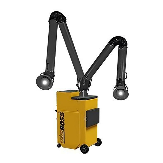
SECTION 200 FEATURES OF THE G120, G121, G122, G123 & G124 1. Vertical Filter Design (Standard): Vertically aligned filters allow the dust to shed off the filter and fall directly down into the containment system. The unique vertical design increases filter life by 30% to 40% over traditional horizontal filter placement. - Page 8 SECTION 200 FEATURES OF THE G120, G121, G122, G123 & G124 (continued) 8. G120 8" Fume Arm with Light Configuration: The G120 is one of industries only single cartridge portables that comes equipped with an 8" fume arm. The arms smooth travel and sturdy positioning make it easy to work in a 270 degree, 16 foot diameter area giving the VentBoss G120 the widest coverage of any portable.
-
Page 9: Receiving & Inspection
SECTION 300 RECEIVING & INSPECTION Receiving VentBoss equipment is typically shipped on skids or in crates. The number of skids/ crates will vary, depending on the type, size and accessories ordered. These skids/ crates are too heavy to lift by hand, and will need to be unloaded by an industrial fork- truck or similar equipment. -
Page 10: General Description
SECTION 400 GENERAL DESCRIPTION VentBoss G100 Series Portable fume extractors allow you it to easily convert from a powerful Fume Arm Extractor to a High Capture Backdraft unit and then to a capable Downdraft Table all in a matter of minutes (with optional equipment). -
Page 11: Installation
SECTION 500 INSTALLATION To operate your new VentBoss Series 100 Portable, you will simply need to set your position, plug it into a dedicated 110 volt 20 amp plug and start welding. After each use, the filter element will need to be back pulsed (see Pulsing the Series 100 Portable). -
Page 12: Operation
SECTION 600 OPERATION Pulsing the Series 100 Portable (Cleaning the Cartridge Filter) The VentBoss Series 100 Portable comes equipped with a Manual Pulsing System (MPS) located just above the cartridge access door. To operate, compressed air must be hooked up to the air inlet. Figure 10. After each days use, press the solenoid plunger 5-15 times to back-flush the filter cartridge. - Page 13 SECTION 600 OPERATION (continued) Installing the Backdraft Plenum (option) To install the optional FlexDraft as a Backdraft Plenum simply replace the Fume Arm connector plate with the FlexDraft Plenum. This is done by releasing the Quick Connect with an 8mm hex wrench. Turn the latch clockwise 1/4 turn to release the plate.
-
Page 14: General Maintenance Procedure
Figure 19. Slide the cartridge out the door and replace with a new RoboVent filter. Figure 20. Replacement filters may be ordered by calling VentBoss at 1-855-558-VENT. - Page 15 SECTION 700 GENERAL MAINTENANCE PROCEDURES (continued) Cleaning the Spark Arrestor Filter The spark arrestor filter should be removed and cleaned on a regular basis. If particulate builds up on the baffle the risk of fire in the system is greatly increased. Typically, the filter should be removed and cleaned with a hot detergent solution every month.
- Page 16 SECTION 700 GENERAL MAINTENANCE PROCEDURES (continued) Solenoid Valve Maintenance The Pulse Solenoid is located just below the blower wheel in the Motor Plenum. Figure 23. Under normal conditions, the pulse valve will last for the life of the collector. Clean, dry compressed air, at 90 PSI, will assure long, maintenance free life of the solenoid.
-
Page 17: Troubleshooting
SECTION 800 TROUBLESHOOTING VentBoss Series 100 Portable is making excessive noise. Check the following: 1. Make sure the blower wheel is not hitting the venturi. 2. Check that all motor bolts are securely tightened. 3. Make sure motor bearings are good. (Amperage rating will be higher than normal.) 4. -
Page 18: Installation, Operation, & Maintenance
SECTION 900 INSTALLATION, OPERATION, & MAINTENANCE General Description & Reservations VentBoss Base Mount Fume Arms are meant for capturing the welding dusts and gases as well as fine dusts, straight at the emission source, in order to avoid expanding the impurities in the process room and being inhaled by people. - Page 19 SECTION 900 INSTALLATION, OPERATION, & MAINTENANCE (continued) The suction hood can be equipped with a halogen spotlight to light up the workspace. In order to install the extraction arm on the wall or column use a wall bracket. It can also be suspended at the end of the RO-type extension arm.
- Page 20 SECTION 900 INSTALLATION, OPERATION, & MAINTENANCE (continued) Connection diagram for hoods with halogen spot-lights: Fume Arm Assembly 1. Take out the VentBoss extraction arm from the package and put it stably on an even surface. 2. Pull the arm segments apart until you obtain the 45° angle. 3.
- Page 21 SECTION 900 INSTALLATION, OPERATION, & MAINTENANCE (continued) Pic. 1 Pic. 2 In case when the extraction arm is installed on a wall bracket, it is important to carry out levelling of the bracket surface while mounting it on a wall. If the bracket is not levelled, the extraction arm is likely not to keep the requested by User work position and tend to fall into one position only (Pic.
- Page 22 SECTION 900 INSTALLATION, OPERATION, & MAINTENANCE (continued) Pic. 3 Pic. 4 VentBoss Fume extraction arms are delivered in cardboard packages in a partly assembled state. Before the extraction arm is installed at the work place – it is important to bring the device into completely assembled state (according to the enclosed instruction).
- Page 23 SECTION 900 INSTALLATION, OPERATION, & MAINTENANCE (continued) Hood with light • Prior to work, start the extraction fan and make sure the ventilation discharge ductwork is functioning. • Set the hood into suitable position: not more than 30 cm from the welding arc, and not less than 20 cm –...
- Page 24 SECTION 900 INSTALLATION, OPERATION, & MAINTENANCE (continued) Using Your VentBoss Fume Arm The construction guarantees a safe and reliable function without continuous servicing and special handling. The adjustment of the ERGO extraction arm consists mainly in corrections within the frictional joints. The frictional brakes are placed in each joint of the d evice and their function is to give the balance and self-supporting properties of the whole extraction arm and ensure an easy manoeuvring during the operation.
- Page 25 SECTION 900 INSTALLATION, OPERATION, & MAINTENANCE (continued) Maintenance & Repair In order to obtain appropriate capture efficiency of the suction hood, clean its surface and the inlet wire-mesh net from the deposited dusts and impurities. In case of welding dusts, additionally – sprinkle the hood with an anti-spattering liquid to avoid adhesing the welding chippings.
- Page 26 SECTION 900 INSTALLATION, OPERATION, & MAINTENANCE (continued) Range of Fume Extraction Arm: ERGO-M/Z 2400 2400 2200 2200 2000 2000 1800 1800 1600 1600 Type D {mm} E {mm} F {mm} L {mm} 1400 1400 ERGO-L/Z-2 65,51 79,72 28,27 90,79 1200 1200 1000 1000...
- Page 27 SECTION 900 INSTALLATION, OPERATION, & MAINTENANCE (continued) 1000 1100 me fl ow [m³/h] fl ow [m³/h] Volume fl ow [m³/h] Range of Fume Extraction Arm: ERGO-D/Z 1800 1600 1400 1200 1000 1000 1200 1400 1600 1800 2000 2200 2400 2600 2000 2200 2400...
- Page 28 37900 Mound Road Sterling Heights, Michigan 48310 USA 855.558.VENT • WWW.VENTBOSS.COM © 2015 RoboVent Product Group...
Need help?
Do you have a question about the VENTBOSS 100 Series and is the answer not in the manual?
Questions and answers