Table of Contents
Advertisement
Quick Links
Advertisement
Table of Contents

Related Manuals for D.C. Athletics Performance 3.0

Summary of Contents for D.C. Athletics Performance 3.0
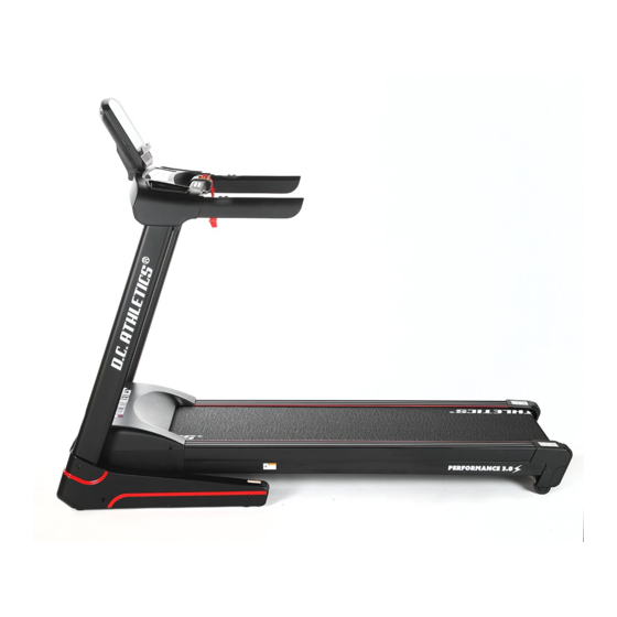
- Page 1 Performance 3.0 MANUAL...
- Page 2 WARNING! Read all instruction carefully before use this product. Retain this owner’s manual for the future’s reference: ----When using this treadmill, keep attaching the safety pull pin rope to your clothes. ----When you are running, keep your hand swinging natural, stare frontward, never look adown at your feet.
- Page 3 IMPORTANT SAFETY PRECAUSTION 1. Plug the power cord of the treadmill directly into a dedicated grounded circuit. This product must be grounded. If it has breakdown, grounding provides a path of least resistance for electric current to reduce the risk of electric shock. 2.
-
Page 4: Assembly Steps
chest, an irregular heartbeat, shortness of breath, feel faint or have any discomfort while you exercise, STOP! Consult your physician before continuing. 16. If you observe any damage or wear on the mains plug or on any section of the mains lead then please have these replaced immediately by a qualified electrician –... - Page 5 STEP 2: 1. Cut down the straps when the main frame was placed well (Don’t move it any more). 2. Connect the Control Board Wire (80) and Extension Wire (79) properly as shown. 3. Attach the Upright Tube (3L/R) onto the Bottom Frame (1) with the Allen bolts (46 & 48), Serrated lock washers (67) and Nylon nuts (72) accordingly.
- Page 6 STEP 3: 1. Connect the Extension Wire (79) with the Computer Wire (78). 2. Attach the Computer Frame (4) onto the Upright Tube (3L/R) with the Allen Bolts (48) and Serrated lock washer (67). 3. Lock all the above mentioned Allen bolts (46 & 48) during Step 2 & 3 tightly. - 5 -...
- Page 7 STEP 4: 1. Attach the Upright Tube Cover (19L/R) to the Computer Lower Cover (16) with Cross tapping screws (58) as shown. 2. Attach the Bottom Frame Cover (26L/R) onto the joint of Bottom Frame (1) and Upright Tube (3L/R) with Cross tapping screws (89). - 6 -...
- Page 8 STEP 5: 1. Connect the Wires of the Panel on the Panel Bracket (6) to the Wires from the Computer Frame (4) properly. (NOTE: Wire Labels of A, B+, B-, C & D should be matched each other.) 2. Using Allen bolts (48) and Serrated l ock washers (67) to secure the Panel Bracket (6) onto the Computer Frame (4).
- Page 9 When you FOLD the Treadmill: Put your hands on position A, lift up the treadmill, then push it as the direction of the arrow, stop it when you hear the sound from the Cylinder (9). NOTE: Unplug the Power Cable and Make Sure the treadmill has Completely STOPPED before folding.
- Page 10 When you UNFOLD the Treadmill: Grasp the position A by your hands, knick the position B of Cylinder (9) by your right foot, pull the running deck to the level of position C, then the running deck will get down automatically. - 9 -...
-
Page 11: Grounding Methods
GROUNDING METHODS This product must be grounded. If it should malfunction or breakdown, grounding provides a path of least resistance for electric current to reduce the risk of electric shock. This product is equipped with a cord having an equipment-grounding conductor and a grounding plug. -
Page 12: Function Specifications
MAX WEIGHT 120KG/ 265LB INCLINE 0 - 15 level OPERATION INSTRUCTIONS 1. Function specifications 1.1. Start Normal startup after 3s counting backwards. 1.2. Number of programs Manual modes, Preset programs, User setting programs, 3 HRC (optional) and FAT. 1.3. Safe lock function Remove the safety lock in any modes could rapidly slow down the treadmill till stop. -
Page 13: Key Function
Restore the safety lock, the window will display for 2s and then get into standby state, wait for inputting commands. 1.4. LCD windows display functions: A. Speed window: display speed data. B. Time/ heart rate window: display time/ heart rate data. Display heartbeat in the operation process first. -
Page 14: Heart Rate Display
parameters of the treadmill. When the treadmill is running, they are used to adjust the incline for 1 grade/time; after holding for more than 2s, automatic continuous increasing or reducing will be realized. There are fast keys on the handrail. ⑧... -
Page 15: Preset Programs
1.8.3. Operation in Manual Mode: A. Press START and the motor will start operating after 3s of countdown; the initial speed will be 1.0km/h for metric system or 0.6mile/h for imperial system; B. Press SPEED +/ SPEED - to adjust speed; C. - Page 16 INCLINE SPEED INCLINE SPEED INCLINE SPEED INCLINE SPEED INCLINE SPEED INCLINE 1.10. User-setting programs: Beside the preset programs, the treadmill has 3 User-setting programs: U1, U2 & U3. 1. Setting the user-defined program: Continuously press "program" key until the expected program (U1/U2/U3) display in the standby condition, while the "time"...
- Page 17 F--4 Weight 20------------150 ≦19 Underweight =(20--24) Normal weight F--5 =(25--29) Overweight ≧30 Obesity 1.12. HRC (optional): DEFAULT is a particular set of instructions which the computer always uses unless the person using the computer gives other instructions. Lowest-Highest: the adjustable range in the heart rate from the lowest to the highest. HRC program Target zone (L-H) Target zone (L-H)
- Page 18 a) The movement time of the heart rate speed was fixed at 22 minutes. b) In standby mode, press “PROG.” key continually until the distance window displays “HRC”. Notes: If press “START” key directly under the HRC display window, the system will automatically recommend a heart rate control parameter for the user as following: HRC can reach a maximum speed of 9.0 km/H, age 30 years, the default setting is 160times/minute.
- Page 19 Notes: 1.HRC must use the chest belt to detect the heart rate and the chest belt must close to the chest and skin. 2. The data collection may be imprecise while using HRC with music playing. 1.13. Others 1.13.1. When a countdown parameter run off, display "END", the alarm rings 0.5s every 2s, until the treadmill full stop, then return to manual mode.
- Page 20 Standby, remove the Safety Key and hold the “STOP" button till “Bi Bi” buzz comes will cancel this remind, and another 300KM later, the remind icon will show up again. 1.16. Meanings of Error message Codes Problem Potential Reasons Solutions 1.
- Page 21 5. After all of these inspections, press the learning key for learning again. 1. It may be the system’s self-protection against excessive current when the load exceeds the rated value; restart the machine; 2. Some part of the treadmill is jammed so that the motor rotate, thus...
-
Page 22: Exercise Instructions
EXERCISE INSTRUCTIONS 1. The Warm Up Phase This stage helps get the blood flowing around the body and the muscles working properly. It will also reduce the risk of cramp and muscle injury. It is advisable to do a few stretching exercises as shown below. -
Page 23: Maintenance Instructions
MAINTENANCE INSTRUCTIONS WALKING BELT CENTERING AND TENSION ADJUSTMENT DO NOT OVERTIGHTEN the walking belt. This may cause reduced motor performance and excessive roller wear. TO CENTER WALKING BELT: ● Place treadmill on a level surface ● Run treadmill at approximately 3.5 mph ●... -
Page 24: Running Belt And Deck Lubrication
WARNING: ALWAYS UNPLUG THE TREADMILL FROM THE ELECTRICAL OUTLET BEFORE CLEANING OR SERVICING THE UNIT. CLEANING General cleaning or the unit will greatly prolong the treadmill. Keep treadmill clean by dusting regularly. Be sure to clean the exposed part of the deck on either side of the walking belt and also the side rails. -
Page 25: Exploded Drawing
EXPLODED DRAWING - 24 -... -
Page 26: Parts List
PARTS LIST - 25 -... - Page 27 Part Part Description Description Bottom frame Hex bolt M8*35 Main frame Hex bolt M8*55 3L/R Upright tube Hex bolt M8*90 Computer frame Allen cylindrical bolt M8*18 Incline frame Allen cylindrical bolt M6*45 Panel bracket Allen cylindrical bolt M6*55 Front roller Allen flat head bolt M6*30 Rear roller Allen flat head bolt M6*25...
- Page 28 Allen bolt M10*55 MP3 cable (Optional) Allen lock bolt M10*55 Audio socket (optional) Allen bolt M10*40 USB (Optional) Allen bolt M8*40 Bluetooth mould Allen bolt M8*50 Inductor (Optional) Allen bolt M8*25 Filter (Optional) Allen bolt M8*15 Loudspeaker (Optional) - 27 -...
Need help?
Do you have a question about the Performance 3.0 and is the answer not in the manual?
Questions and answers