Table of Contents
Advertisement
Quick Links
Advertisement
Table of Contents

Related Manuals for Kobold KUP Series


Summary of Contents for Kobold KUP Series
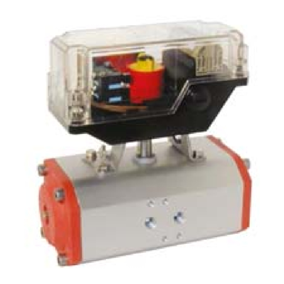
- Page 1 Operating Instructions Ball Valves with Pneumatic Actuator Model: KUP-...
-
Page 2: Table Of Contents
Order Codes ....................28 Dimensions [mm] ..................31 EC Declaration of Conformance ..............35 Manufactured and sold by: Kobold Messring GmbH Nordring 22-24 D-65719 Hofheim Tel.: +49(0)6192-2990 Fax: +49(0)6192-23398 E-Mail: info.de@kobold.com Internet: www.kobold.com page 2 KUP K02/0522... -
Page 3: Note
The instruction manuals on our website www.kobold.com are always for currently manufactured version of our products. Due to technical changes, the instruction manuals available online may not always correspond to the product version you have purchased. -
Page 4: Safety Notes
5. Safety notes You must pay attention to special safety aspects depending on the prevailing technical conditions and the time at which you install and adjust the actuator, and put it into operation! For example, you will be exposed to much greater risks when placing the device in operation if you open or close a pipe in an operational chemical plant with the pneumatically operated ball valve than when you place the device in operation for test purposes at a "dry"... -
Page 5: Safety Of Machinery
5.1.2. Safety notes for adjustment / starting As a result of the starting (pneumatic or by hand) of a pneumatic actuator the position of a flanged slide/valve/flap will be changed! Therefore, the flow of gases, steam, liquids, etc. may be enabled or interrupted! ... -
Page 6: Operating Principles
The operation of the pneumatic actuator beyond the admissible temperature range will overburden or damage the sealings and bearing. The operation of the pneumatic actuator beyond the admissible working pressure will damages the internal parts and the body. ... -
Page 7: Function „Single-Acting
Description of function, double-acting 6.4. Function „single-acting“ Pressure is given through port „P1“ into the actuator between the two piston surfaces. The pistons expand against the spring force. The pistons force will be transfer to the pinion by racks. The pinion turns round counterclockwise about 90° ->the actuator moves into the position „OPEN“. -
Page 8: Rotation Direction
7. Rotation Direction The pneumatic actuators are available as „right revolving“ or „left revolving“ actuators. The standard rotation direction is to turn left. The rotation direction of the pinion of the pneumatic actuator will be counterclockwise to be open and clockwise to be close. -
Page 9: Change Of The Rotation Direction At Actuator With Function „Double-Acting
7.2. Change of the rotation direction at actuator with function „double-acting“ Loosen the cap bolts (1). At single-acting pneumatic actuators the changing of the rotation direction will be permitted only by the manufacturer. Do not loosen or screw out the cap bolts. - Page 10 Turn around the pistons (1) about 180°, don’t take the pistons out of the body (2) at this (see Fig.) Insert the piston (1) into the body, so that both racks (3) will mesh into the teeth of the shaft (4) at the same time. Observe the turning direction of the shaft. Turn the shaft counterclockwise with a spanner until the groove of the shaft will be at right angles to the axle of the actuator.
-
Page 11: Ambient Conditions
8. Ambient conditions The pneumatic actuator KUP is designed for industrial operating conditions! However, some special conditions are to be observed for its mounting and subsequent operation! Take care that the actuator is mounted in accordance with the mounting advice listed below. - Page 12 A mounting with bracket and stem will be necessary, if the differences of the dimensions between the shaft of the actuator and the stem of the slide/valve/flap are not able to be equalized by a bushing or the ISO-flanges did not match. This mounting variant will also be used by high/low medium temperatures or voluminous isolated pipes.
- Page 13 9.1.2. Mounting by bracket and stem Ensure that the actuator and the slide/valve/flap will be in position „CLOSE“. Put the stem onto the stem of the slide/valve/flap. Therefore, observe the position of possibly position indicators. Put the bracket onto the slide/valve/flap and align them. Fasten the bracket with fit bolts.
-
Page 14: Pneumatically Installation
Fasten the actuator with fit bolts. Observe the maximum depth of the threaded holes of the actuator. Would there be two sizes of hole circles to fasten the actuator, you have always to use the greater one. Tighten the screws. Therefore, observe the maximum torque of the chosen screws. - Page 15 If appropriate lay the hoses in conduits or cable ducts. As an alternative to the shown variant the control of the actuator could take place by a directly mounted pilot valve. In this case see the enclosed operation and installation manual of the pilot valve. 9.2.1.
-
Page 16: Disassembly
Screw in a suitable pneumatic fitting (e.g. Art. C12xx or R12xx) into the port „P1“ by using a fit sealing compound and tighten the fitting. Insert a hose into the fitting at port „P1“ which will feed the actuator with compressed air during the opening operation. -
Page 17: Adjustment/Starting
Never remove an armature under pressure. Ball valves are able to enclose the pressurize medium. Release the pressure in the pipes, to relieve the pressure at the armature. 9.3.1. Pneumatically disassembly Turn the actuator with the slide/valve/flap into its fix position! Switch off the compressed air supply and the control of the actuator! If necessary, set up warning signs in order to prevent ... -
Page 18: Starting
Never adjust the adjusting screws against the efficacy of pressure. Put the pistons of the actuator together by feeding the port „P2“ with compressed air (only function double-acting), or exhausted port „ P1“ (only function single- acting). Loosen the nuts (1) in both caps. Turn one of the adjustment screws (2) into the cap (3), until the screw aligns with the cap or the screw will be deeper about max. -
Page 19: Emergency Operation
Actuate the pneumatic actuator by hand with the control and check the correct function of the actuator and the mounted slide/valve/flap. Check all pipe connections for tightness. Check all the pilot leads for tightness. Check the function of the accessory units. 11. -
Page 20: Failure
12. Failure If, during the test run or during operation, a functional fault of the pneumatic actuator should occur, you are requested to carry out the adjustment of the slide/valve/flap (in an emergency) by hand. See also chapter 11 Emergency Operation. -
Page 21: Mounting Of The Spare Part Kit
If you determine that there is a damage to the actuator, isolate it from the pilot pressure and the power supply. However, before doing this, it is essential to refer to the Safety advice (chapter 5). In dependence of the environment the replacement of the sealings and guide rings will be necessary at ca. - Page 22 Maintenance – Mounting of the spare part kit Remove the spring clip (6) from the shaft by fit tongs. Take off the bearing bush (7). Take off the shaft from the body by pressing it downwards . Do not drop the shaft with the pinion.
- Page 23 Insert new sealings and guide rings. Observe that the parts are undamaged and that they are placed in a correct way. Apply a light film of grease to all sealings and on the gear teeth by a grease recommended by Kobold. KUP K02/0522 page 23...
- Page 24 Maintenance - Mounting of the spare parts kit Mounting Insert the shaft (1) from the bottom into the body (2) and push it in to the stop. Observe that no sealing and no guide ring will be damaged. Push the bearing bush (3) over the top of the shaft. Mount the spring clip (4) in the groove of the shaft by fit tongs.
- Page 25 Put the new cap seals (4) into the sealing groove of the cap (5). Check the right placement of the seals. Put the cap onto the body and align it. Screw in the bolts (6) with the washers(7) into the body and tighten them up crosswise. Maintenance - Mounting of the spare parts kit Check the function and if necessary adjust the limit stops.
-
Page 26: Cleaning
13.3. Cleaning Clean the body of the pneumatic actuator as required using a slightly moistened, soft cloth and a normal household cleaner. Do not use any abrasive, corrosive or flammable cleaning agents! Do not use any high-pressure cleaning devices! Prevent moisture or liquid penetrating into the interior of the actuator! 14. -
Page 27: Device Description
15. Device Description Device description 1 body 2 cap 3 cap bolt 4 limit stop bolt 5 nut 6 shaft for signal devices 7 fastening thread for signal devices (M5 x 7) 8 pilot port P1 9 pilot port P2 10 fastening thread for control devices(M5 x 8) 11 fastening thread for slide/valve/ flap 12 shaft for slide/valve/flap... -
Page 28: Order Codes
16. Order Codes KUP-KA Order Details (example: KUP-KA R15 C A 0) Model Connection Actuation Solenoid valve Limit size switch A = without C = single-acting, R15 = Rp ½ B = 3/2 way default CLOSED R20 = Rp ¾ (24 V O = single-acting, R25 = Rp 1... - Page 29 KUP-VH Order details (example: KUP-VH R15 C A 0) Model Connection Actuation Solenoid valve Limit size switch A = without C = single-acting, B = 3/2 way default CLOSED R15 = G ½ (24 V O = single-acting, R20 = G ¾ C = 3/2 way 0 = without default OPEN...
- Page 30 KUP-VO Order details (example: KUP-VO F25 C A 0) Model Connection size Actuation Solenoid valve Limit switch A = without C = single-acting B = 3/2 way CLOSED (24 V O = single-acting, C = 3/2 way F25 = DN25 OPEN (230 V F32 = DN32...
-
Page 31: Dimensions [Mm]
17. Dimensions [mm] 3/2-way solenoid valve for single-acting actuators 5/2-way solenoid valve for double-acting actuators KUP K02/0522 page 31... - Page 32 Electric-mechanic limit switches in protective casing KUP-KA KUP-ZA page 32 KUP K02/0522...
- Page 33 KUP-VH KUP-VN KUP-PD KUP K02/0522 page 33...
- Page 34 KUP-VO KUP-VK page 34 KUP K02/0522...
-
Page 35: Ec Declaration Of Conformance
18. EC Declaration of Conformance We, KOBOLD Messring GmbH, Hofheim-Ts, Germany, declare under our sole responsibility that the product: Ball valve with pneumatic actuator KUP-... to which this declaration relates is in conformity with the standards noted below: EN ISO 12100:2011-03... - Page 36 Additional for devices with solenoid valve: 2014/35/EU Low Voltage Directive 2014/30/EU EMC Directive DIN EN ISO 12100:2011 Safety of machinery - General principles for design - Risk assessment and risk reductionE DIN EN 60204-1:2014 Safety of machinery - Electrical equipment of machines - Part 1: General requirements Additional for devices with limit switches: 2014/35/EU...
Need help?
Do you have a question about the KUP Series and is the answer not in the manual?
Questions and answers