Advertisement
Quick Links
Thank you for purchasing the Xantrex Solar Max Flex Panel. The Xantrex Solar Max Flex Panel is a
high quality, carbon emissions-free, and sustainable power source for your vehicle such as,
recreational vehicle (RV), truck, or boat. It is designed to take solar energy and quietly produce power
for your vehicle's DC appliances and store energy to a battery during daylight hours.
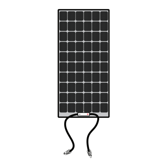
The Solar Max Flex Panel base package includes the
following items:
one Solar Max Flex Panel
n
one Product Notice with a link to this Installation
n
Guide
NOTE: If any of the accessories, materials, and other
items are missing, contact Xantrex or any authorized
Xantrex dealer for replacement. See Contact Information
on the back cover.
The following Xantrex accessories are available to complete your solar system and are sold
separately:
Solar and Battery Cables Starter Kit (PN: 708-0150)
n
PWM 30A Charge Controller (PN: 709-3024-01)
n
MPPT 30A Charge Controller (PN: 710-3024-01)
n
MPPT Remote Display (PN: 710-0010)
n
Installation Guide
110W Solar Max Flex Panel
Model Number: 784-0110
110W Solar Max Flex Slim Panel
Model Number: 784-0110S
220W Solar Max Flex Panel
Model Number: 784-0220
330W Solar Max Flex Panel
Model Number: 784-0330
NOTE: Actualproduct maybe different from what isshown.
Advertisement

Related Manuals for Solar Xantrex 784-0110


Summary of Contents for Solar Xantrex 784-0110
- Page 1 Model Number: 784-0330 NOTE: Actualproduct maybe different from what isshown. Thank you for purchasing the Xantrex Solar Max Flex Panel. The Xantrex Solar Max Flex Panel is a high quality, carbon emissions-free, and sustainable power source for your vehicle such as, recreational vehicle (RV), truck, or boat.
- Page 2 To reduce the risk of electrical shock, disconnect the solar max flex panel from all devices and or components before attempting any maintenance or cleaning on the solar max flex panel.
-
Page 3: Table Of Contents
Contents Basic Installation Steps Safety Instructions Tools and Materials Solar Panel Wiring Solar Panel Maintenance and Care Troubleshooting Specifications Accessory List 975-1029-01-01 Rev B June 2022... - Page 4 This page is intentionally blank.
-
Page 5: Basic Installation Steps
WARNING ELECTRICAL SHOCK AND FIRE HAZARD The power system must be designed by a certified vehicle solar system designer and installed by a certified solar system technician. All wiring should be done by qualified personnel to ensure compliance with all applicable installation codes and regulations. - Page 6 Plan the route and measure the lengths of cables needed to reach their connection points factoring in bends and slack. d. You may add additional solar panels. For more information, see Solar Panel Wiring on page 10. WARNING ELECTRIC SHOCK AND FIRE HAZARD Do not ground any PV conductors.
- Page 7 The backside of the Solar MaxFlexPanelhas3M VHBtape stripsalreadyapplied around the perimeter of the panel. c. Peel off the liner film from the 3M VHB tape and place the Solar Max Flex Panel on the exact and intended location. It is ideal to have two people to carefully and accurately mount the solar panel.
- Page 8 For illustration purposes. The solar cellsare shown asperspective only. Do not applythe adhesive tape on top of the solar cells. The adhesive tape must be applied on the backside of the paneland onto the mounting surface. 975-1029-01-01 Rev B...
- Page 9 (black). Failure to follow these instructions can result in equipment damage. a. Cover the solar panel with a blanket (or the packaging box) to de-energize it. b. Connect the red pos (+) and black neg (–) PV cables to the solar panel using the MC4-type connectors.
-
Page 10: Solar Panel Wiring
12/24VDC 710-3024-01 b. Solar panels can be configured in series, parallel, or a combination of both series and parallel. Figure 5 Cable schematic for series Pos (+) of first panel connects to Neg (-) of next panel and so on and terminating with the Pos (+) of the solar charge controller. - Page 11 Pos (+) of first panel connects to Pos (+) of next panel using branch connectors and so on and terminating with the Pos (+) of the solar charge controller. Neg (-) of first panel connects to Neg (-) of next panel using branch connectors and so on and terminating with the Neg (-) of the solar charge controller.
-
Page 12: Solar Panel Maintenance And Care
The power output of a solar panel is proportional to the amount of sunlight that reaches Solar the solar cells. Therefore, any build-up of dust or dirt on the surface of the solar panel will Panels result in a loss of power. This is a trade-off between the maximizing the power output of the solar panel versus the cost and time to perform regular cleaning. -
Page 13: Troubleshooting
Solar panel is partially shaded Move the vehicle or vessel so the whole even when sunlight is or there is insufficient sunlight. solar panel is exposed to direct sunlight. present. Loose or no DC cable Connect DC cables to the battery and connections. - Page 14 110W Solar Max Flex Slim Panel Part number 784-0110S Dimensions 73.7 × 14.8 × 0.08 inches (1871 × 376 × 2 mm) Unit weight 6.1 lbs.(2.8 kg) Cell Type Monocrystalline PERC Maximum power at STC* 110 W Maximum power voltage 24.6 V Maximum power current 4.5 A Open circuit voltage 29.2 V Short circuit current 4.8 A...
-
Page 15: Accessory List
30A PV Branch Connector (PN: PV Connector Assembly Tool 15-ft (PN: 708-0030) 708-0040) 708-0050) (PN: 708-0060) Solar and Battery Cables Starter Mounting Hardware (PN: 708- Remote Battery Temperature Roof-Entry Cable Plate (PN: Kit 10 AWG, 20-ft PV cables, 10-ft 0070) - Page 16 +1-800-670-0707 +1-408-987-6030 customerservice@xantrex.com http://www.xantrex.com/power-products-support/ http://www.xantrex.com 975-1029-01-01 Rev B Printed in USA. June 2022...
Need help?
Do you have a question about the Xantrex 784-0110 and is the answer not in the manual?
Questions and answers