Table of Contents
Advertisement
Quick Links
Advertisement
Table of Contents

Related Manuals for K-Rain PRO EX 2.0


Summary of Contents for K-Rain PRO EX 2.0
- Page 1 WIFI ENABLED MODULAR CONTROLLER INSTRUCTION MANUAL...
-
Page 2: Table Of Contents
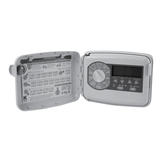
Connecting the Flow Sensor Valve Locator INTRODUCTION Pump Start/Master Valve Wiring Test All Stations The PRO EX 2.0 WiFi Enabled Controller is available as indoor or Rain Sensor Installation Special Features outdoor models, with both modules utilizing a WiFi enabled Hub. Remote Programming... -
Page 3: Controls And Touch Pad
Installation, Programming and Operation Manual CONTROLS AND TOUCH PAD LCD DISPLAY MANUAL START / LCD DISPLAY NEXT BUTTON Displays the time of day MANUAL START / Used to start a selected and day of the week BACK DOWN NEXT BUTTON irrigation program BUTTON BUTTON... -
Page 4: Setting The Controller To Off
PROGRAM SELECT BUTTON 1. Turn the dial to “OFF” 1. Turn the dial to “AUTO” The PRO EX 2.0 controller has three separate programs, A, B and C. When the dial is in the “OFF” position no When the dial is in the “AUTO” position Multiple programs allow valves watering occurs. -
Page 5: Rain Sensor Select Button
Installation, Programming and Operation Manual RAIN SENSOR SELECT BUTTON PROGRAMMING The purpose of a rain sensor is to stop A key feature of the PRO EX 2.0 controller automatic watering when sufficient is its large easy-to-read LCD display. Only one start time per program precipitation has been reached. -
Page 6: Set Time/Date
DOWN or UP buttons until “OFF” current minutes. appears in the display. The OFF setting is NOTE: The PRO EX 2.0 controller can be set for located between 11:45 p.m. and 12:00 a.m. 5. To set the current date, press the NEXT button. -
Page 7: Set Watering Days
Installation, Programming and Operation Manual SET WATERING DAYS SET CUSTOM OPERATION SET ODD/EVEN OPERATION The PRO EX 2.0 controller can be 1. Use the PROGRAM SELECT BUTTON 1. Use the PROGRAM SELECT BUTTON programmed to operate within four to select the program (A, B or C) you wish to select the program (A, B or C) you different watering cycles. -
Page 8: Set Cyclic Watering Cycle
SET CYCLIC WATER CYCLE SET STATION RUN TIMES 1. Use the PROGRAM select button to select Stations 1–28 can be set to run from one NOTE: Station run times can be set to the program (A, B or C) you wish to assign cyclic second up to six hours. -
Page 9: Manual Program Operation
For RF Module installation, Pin Code FRI 9:09 programming and operation please 4. The display will show “RUN,” the station refer to the optional PRO EX 2.0 remote currently running and the remaining run time user manual. for that station. As each station completes its previously programmed run time the next station in sequence will begin watering. -
Page 10: Running A Single Station Manually
Previously programmed run times can be station you wish to manually operate. increased or decreased during manual The PRO EX 2.0 controllers locate feature operation. Any run time changes during helps the user find buried valves by pulsing 2. Turn the dial to RUN SINGLE STATION. -
Page 11: Test All Stations
Installation, Programming and Operation Manual TEST ALL STATIONS NOTE: Changing the test run time can be done The PRO EX 2.0 allows the user a quick and simple method for checking all available at anytime and for any station during the test. -
Page 12: Special Features
SPECIAL FEATURES SEASONAL ADJUST STATION DELAY/OVERLAP PUMP ON / OFF NOTE: This feature is not able to be set remotely NOTE: This feature is not able to be set The seasonal adjust feature allows the user to increase or decrease station run times globally, via smartphone, tablet or browser. -
Page 13: Sensor
Installation, Programming and Operation Manual SENSOR OPEN CIRCUIT DETECTION CLEAR NOTE: If the controller is connected to the The SENSOR on/off feature allows the user The open circuit detection feature prevents pump to enable or disable the SENSOR terminals for and station operation when the controller detects INTERNET, and the program settings have each individual station. -
Page 14: Save
SPECIAL FEATURES SAVE RESTORE DISPLAY CONTRAST The SAVE feature allows the user to save to restore any previously saved programs. all current programming. This allows the user 1. Turn the dial to SPECIAL FEATURES. to quickly and easily restore any saved 1. -
Page 15: Permanent Day Off
Installation, Programming and Operation Manual DAY OFF Permanent days off programmed through special 3. Press the UP or DOWN buttons to enable features will not display on program features OR (turn on) the day off feature. The display will now in the smartphone/tablet interface show a solid (non-flashing) “MON.”... -
Page 16: Set Flow Meter
SPECIAL FEATURES SET FLOW METER Using a flow sensor in conjunction with your 3. Then press the NEXT button until FLOWMTR 5. After “SELSIZE” is displayed, push NEXT controller allows you to monitor, control, and is displayed. Push NEXT to select. to select and proceed to choose the react to real-time water flow conditions. -
Page 17: Set Optional Hi/Lo Flow Limits
Installation, Programming and Operation Manual SET OPTIONAL HI/LO FLOW LIMITS Using the HI/LO flow limits feature allows you to fine 2. Press the NEXT or BACK button until This default is set to “BY PROGRAM”, tune your flow sensing. Setting these limits helps in SET MTR is displayed. -
Page 18: Setting By Program
SPECIAL FEATURES SETTING BY PROGRAM 1. Push NEXT to select BY PROGRAM. 2. Push the UP button to start the Low setting 4. Continue to use UP or DOWN buttons until at 1 Gallon Per Minute (GPM) or alternatively you reach your desired HI flow limit setting. push the DOWN button to start at 500 GPM. -
Page 19: Setting By Zone
Installation, Programming and Operation Manual SETTING BY ZONE 1. Push NEXT to select BY ZONE. 2. Push the UP button to start the LO setting at 5. Continue to use the UP or DOWN buttons 1 Gallon Per Minute (GPM) or push the DOWN until you reach your desired high flow limit button to start at 500 GPM. -
Page 20: Flow History
SPECIAL FEATURES FLOW HISTORY The flow history function allows the user to view one 2. Press the NEXT or BACK button until FLOHIST 4. Use the UP or DOWN buttons to toggle week’s worth of stored flow data. It will show how is displayed ”LO”... -
Page 21: Set Flow Units
Installation, Programming and Operation Manual SET FLOW UNITS This feature allows you to switch back and 3. Use the UP and DOWN buttons to toggle forth between Gallons Per Minute (shown back and forth to Liters Per Minute (L). as G) or Liters Per Minute. (shown as L). To Set the Flow Data Units that the Controller UNIT L will Display:... -
Page 22: See Live Flow Data
SPECIAL FEATURES SEE LIVE FLOW DATA This feature allows the user to see live flow data 2. Press the NEXT or BACK button until in a few different ways. You can view the data GPM N:A is displayed. This screen will be remaining run time RUN 4:25 under Special Features while a Program is running or... -
Page 23: Possible Alarm Displays
Installation, Programming and Operation Manual POSSIBLE ALARM DISPLAYS The following are possible alarms that could be dis- FLOW HI H2OLEAK played in conjunction when using a flow meter with This is the alarm that will show if your system The H20LEAK is an alarm that is triggered when this controller. -
Page 24: Program Display
PROGRAM DISPLAY RESETTING THE CONTROLLER The PRO EX 2.0 program display feature The reset button is used to reset the 3. Close the panel by swinging it back provides a complete visual overview of controller. All programming information to the right and press until it locks into any program contents. -
Page 25: Installation
Installation, Programming and Operation Manual INSTALLATION DOOR REMOVAL MAIN PANEL REMOVAL The PRO EX 2.0 controller can be installed 1. Making sure the door is unlocked, open 1. Open the front panel by grasping the either indoors or outdoors and must be done... -
Page 26: Mounting The Controller
MOUNTING THE CONTROLLER The PRO EX 2.0 controller has a single Making sure the controller is level, The PRO EX 2.0 controller has four keyhole slot on the top / back of the controller. Three drive an appropriate fastener(s) in “knockout”... -
Page 27: Installing A 4 Station Module
INSTALLING A 14 STATION MODULE The PRO EX 2.0 controller is supplied with a factory installed four The PRO EX 2.0 controller is supplied with a factory installed four station station module and can be expanded up to 16 stations by use of module and can be expanded up to 16 stations by use of additional four additional four station expansion modules. -
Page 28: Module Layout Combinations
MODULE LAYOUT COMBINATIONS Shown below are the possible module layouts and what the new station numbers would be with those combinations of modules. | www.krain.com... -
Page 29: Installing A 14 Station Module
Installation, Programming and Operation Manual INSTALLING A 14 STATION MODULE CONNECTING VALVE WIRES CONNECTING THE FLOW SENSOR To install a second 14 station module, 1. Connect each valve with its individual 1. Connect the black wire to the negative (-) terminal. simply follow the previous steps but power wire to one of the numbered screw Connect the red wire to the positive (+) terminal. -
Page 30: Pump Start/Master Valve Wiring
NOTE: If a rain sensor has not been connect all unused stations to the last station with a installed in the PRO EX 2.0 controller, the run time. pre-installed jumper wire must remain installed on the SENSOR terminals. -
Page 31: Remote Programming
REMOTE PROGRAMMING POWERING THE CONTROLLER NEUTRAL (Orange) The PRO EX 2.0 controller allows the user to It is recommended that a licensed electrician perform The PRO EX 2.0 controller is powered program the controller with the main panel the following power installation. -
Page 32: Specifications
• Station Run Times: • Transformer Input: 1 second to 6 hours on 115VAC, 60Hz or 220 VAC, 50/60Hz The PRO EX 2.0 controller is powered programs A, B and C. with either 115VAC or 220VAC which • Transformer Output: must be noted when ordering the unit. -
Page 33: Troubleshooting
Installation, Programming and Operation Manual TROUBLESHOOTING SYMPTOM POSSIBLE CAUSE CORRECTION SYMPTOM POSSIBLE CAUSE CORRECTION Dial set to the OFF position Set dial to AUTO No Station Run Time has Turn the Dial to SET STATION RUN been set TIMES and check program station No Start Time Turn the dial to PROGRAM DISPLAY for run time... -
Page 34: Quick Programming Reference Guide
QUICK PROGRAMMING REFERENCE GUIDE | www.krain.com... -
Page 35: Spare Watering Planner
Installation, Programming and Operation Manual SPARE WATERING PLANNER WATERING SCHEDULE PROGRAM A PROGRAM B PROGRAM C WATERING SCHEDULE PROGRAM A PROGRAM B PROGRAM C CUSTOM-- CUSTOM-- ODD/EVEN-- ODD/EVEN-- CYCLIC-- CYCLIC-- WATERING START TIMES WATERING START TIMES STATION STATION LOCATION STATION RUN TIMES STATION STATION LOCATION STATION RUN TIMES... -
Page 36: Warranty
Hereby, K-Rain Manufacturing Corporation declares that this accessories used in the equipment covered under this warranty or to irrigation controller PRO EX 2.0 is in compliance with the essential any damage which may be caused by such batteries. requirements and other provisions of Directive 1999/5/EC.
Need help?
Do you have a question about the PRO EX 2.0 and is the answer not in the manual?
Questions and answers