Table of Contents
Advertisement
Quick Links
Advertisement
Table of Contents

Related Manuals for K-Rain SITEMASTER 3400


Summary of Contents for K-Rain SITEMASTER 3400
- Page 1 2-Wire Decoder Controller Instruction Manual...
-
Page 2: Table Of Contents
TABLE OF CONTENTS Declaration of Conformity Program A Decoder Pump Pressurization Specifications Use Decoder Port Save Program Dimensions Manually Enter Decoder Number Restore Program Operating Specifications Set Decoder as Master Valve Clear Program Set Decoder as Pump Start Default Settings Factory Reset Electrical Specifications Sync a Multi-station Decoder... -
Page 3: Declaration Of Conformity
Watering (2) increase the separation between the Con g. Days SET DATE NOV 19 the use of a K-Rain 1520 or 1510 Mini Coil relay. equipment and receiver; Program Remote Pump Start relays running with a decoder on ERROR Decoder... -
Page 4: Sitemaster Special Features
• Set Hrs./minutes to Minutes/Seconds by Program. • Hard wired terminals dedicated to rain sensor, as well Hrs./Minutes default as functions with a K-Rain wireless rain sensor • Coin cell battery in the midbox to support non-volatile battery. • Moisture sensors on decoders No AAA batteries. -
Page 5: General Introduction
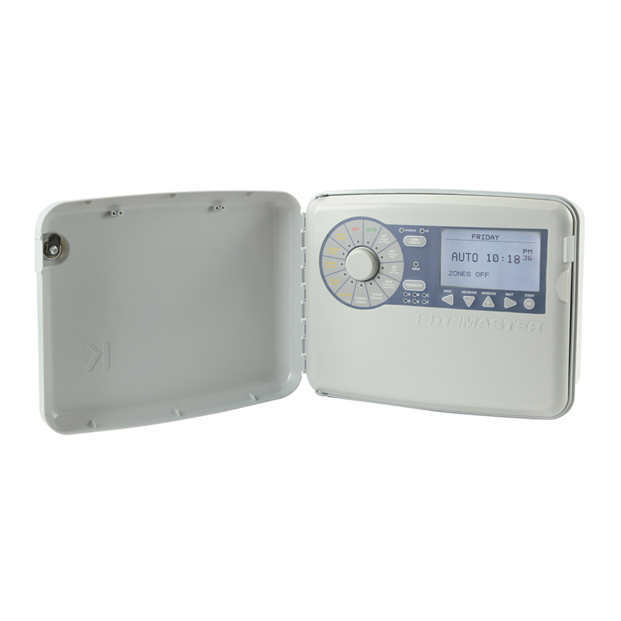
Installation, Programming and Operation Manual GENERAL INTRODUCTION MIDBOX FEATURES AUTO DISABLED NAME A ZONE Digital Dial with Rain Sensor Bypass Error / Alarm LED Large 3" x 5" Sensor RAIN Program LED indicator Select Button Config. LCD Display Start Times SENSOR Front Lawn 1 ZONE 1... -
Page 6: Dial Features
GENERAL INTRODUCTION DIAL FEATURES Flow Meter Type Set Flow Limits Volume Counts Set Weather Station Set Controller Date/Time Set Moisture Sensors Standard/Metric Set Wireless Rain Sensor 24hr/12hr Name Program Set 6 separate start times Display Current Load for each of the 6 programs AUTO DISABLED Display Live Flow Data... -
Page 7: Controller Components
Installation, Programming and Operation Manual GENERAL INTRODUCTION CONTROLLER COMPONENTS 40VA WITH 3 AMP FUSE 120,240 24VAC 100VA WITH 5 AMP BREAKER 120,240 27VAC 3403- 2 WIRE 3206- RF MODULE 3404- MODULE FOR THE WIRELESS NETWORK RAIN SENSOR MODULE 9V BATTERY FOR REMOTE PROGRAMMING MODULE FUSE LOCATIONS 3403- 2 WIRE... -
Page 8: Line Definition
GENERAL INTRODUCTION LINE DEFINITION MAIN FUSE LOCATIONS The SiteMaster features 4 total wire paths from 2 independent sources: Line 1 – A & B, Line 2 – A & B. To make wiring easy, use the color coded arrows when installing 2-wire line. -
Page 9: Keyboard Layout
Installation, Programming and Operation Manual GENERAL INTRODUCTION KEYBOARD LAYOUT When using the on-screen keyboard, use the arrows OR the dial, NAME ZONE 02 navigate the curser around the keyboard to highlight the desired letter or number, then push OK. Then scroll the curser to NEXT and push the arrow to confirm NORTH SIDE... -
Page 10: Basic Decoder Installation
BASIC DECODER INSTALLATION SINGLE STATION DECODER INSTALLATION RED AND BLACK SOLID WIRE FROM THE DECODER TO THEIR CORRESPONDING CABLES ON THE 2-WIRE PATH, CONNECTED WITH DBR-6, DBY-6 CONNECTORS OR EQUIVALENT DECODER YELLOW BRAIDED WIRE FROM THE DECODER TO THE SOLENOID. CONNECTED WITH DBR-6, DBY-6 CONNECTORS OR EQUIVALENT 2-WIRE PATH... -
Page 11: 2-Station Decoder Installation
Installation, Programming and Operation Manual BASIC DECODER INSTALLATION 2-STATION DECODER INSTALLATION RED AND BLACK SOLID WIRE FROM THE DECODER TO THEIR CORRESPONDING CABLES ON THE 2-WIRE PATH, CONNECTED WITH DBR-6, DBY-6 CONNECTORS OR EQUIVALENT 2-STATION DECODER MAX 100’ IF THE VALVES BEING CONNECTED ARE IN SEPARATE VALVE BOXES, THE MAXIMUM YELLOW BRAIDED WIRE FROM 2-WIRE PATH... -
Page 12: 4-Station Decoder Installation
BASIC DECODER INSTALLATION 4-STATION DECODER INSTALLATION RED AND BLACK SOLID WIRE FROM THE DECODER TO THEIR CORRESPONDING CABLES ON THE 2-WIRE PATH, CONNECTED WITH DBR-6, DBY-6 CONNECTORS OR EQUIVALENT 4-STATION DECODER YELLOW BRAIDED WIRE FROM THE DECODER TO THE SOLENOID. CONNECTED WITH DBR-6, DBY-6 CONNECTORS... -
Page 13: Basic Surge Protector Installation
Installation, Programming and Operation Manual BASIC SURGE PROTECTOR INSTALLATION The minimum recommended surge protection is one grounded surge protector at the beginning and end of each wire path and a grounded surge protector every 1,000 ft/300m or every 12 decoders, whichever comes first. This is the minimum amount. For greater protection the system can be grounded more frequently. -
Page 14: Grounding Specifications
GROUNDING SPECIFICATIONS CONTROLLER GROUNDING DECODER/SURGE PROTECTOR GROUNDING The controller will be grounded with a Paige Surge protectors should be grounded with a 182007 (10ft copper clad rod) or equivalent ground plate and/or grounding rod (Plate: Paige and a Paige 182199IC grounding plate (4” x 96” 182199/182201;... -
Page 15: Installation
Installation, Programming and Operation Manual INSTALLATION DOOR REMOVAL MAIN PANEL REMOVAL The Sitemaster controller can be installed 1. Making sure the door is unlocked, open 1. Open the front panel by grasping the either indoors or outdoors and must be installed the enclosure door and swing it to the left finger hold on the top right side of the in compliance with local electrical codes. -
Page 16: Mounting The Controller
MOUNTING THE CONTROLLER POWERING THE CONTROLLER The SiteMaster has three “knockout” plugs available for routing valve, pump start and The SiteMaster has two keyhole slots on the top / It is recommended that a licensed electrician sensor wires. All are located on the bottom back of the controller. -
Page 17: Controller Configuration
Installation, Programming and Operation Manual CONTROLLER CONFIGURATION SET DATE SET TIME The CONTROLLER CONFIG. dial position is used to set: With this feature, you will be setting the With this feature, you will be setting the time actual calendar date used in programming clock used in programming the controller. -
Page 18: Set Imperial/Metric
CONTROLLER CONFIGURATION SET IMPERIAL OR METRIC SET 12 / 24 HR CLOCK NAME PROGRAM With this feature, you will be setting how the With this feature, you will be telling the This feature allows you to rename any of the controller displays numeric values, either controller to display a 12 hour clock or 6 preset program names (A,B,C,D,E, &... -
Page 19: Display Current
Installation, Programming and Operation Manual CONTROLLER CONFIGURATION DISPLAY CURRENT DISPLAY FLOW This will turn the line display on the AUTO screen. This feature allows the user to display This feature allows the user to display the the active current draw on each line active current flow rate being measured by AUTO independently on the main display screen. -
Page 20: Program A Decoder
PROGRAM A DECODER AUTO TO SYNC A SINGLE STATION DECODER 3. Then go back to the midbox face and 6. Use the arrows to move Sensor push OK to start. The controller will take the curser to the zone you wish to add USING THE PROGRAMMING PORT Program Con g. -
Page 21: Manually Enter Decoder Number
Installation, Programming and Operation Manual PROGRAM A DECODER TO SYNC A SINGLE STATION 3. Once complete, using the arrows AUTO DISABLED ASSIGN OOOOOO scroll the curser all the way to the right, then DECODER USING MANUAL ENTRY AUTO Sensor push the s arrow to move it up to the NEXT Program RAIN Con g. -
Page 22: Set Decoder As Master Valve
PROGRAM A DECODER AUTO TO SET A SINGLE 3. The controller is now asking which 3. The controller is now asking which line Sensor Program line you are going to use this decoder on. you are going to use this decoder on. Use STATION DECODER Con g. -
Page 23: Name Zone
Installation, Programming and Operation Manual PROGRAM A DECODER AUTO REMOVE ZONE 3. The controller will now ask if you are NAME ZONE Sensor Program This feature allows the user to remove sure you want to remove the chosen zone. Con g. This feature allows the user to Start Times a zone that has been assigned. -
Page 24: Reassign A Decoder
PROGRAM A DECODER REASSIGN A DECODER 3. The next screen will ask you to confirm 6. Use the t/s arrows to move the the decoders serial number. If this is correct, to the new line this decoder will be This feature allows the user to reassign a use the arrows, OR the Dial to move assigned to and push OK. -
Page 25: Programming
Installation, Programming and Operation Manual PROGRAMMING SET PROGRAM START TIMES 2. Continue to use t/s arrows to change AUTO the Hour Position to the desired setting. Displays: Setting Program Start Sensor 1. OFF times or watering days NOTE: When the hour position is cycled Program Con g. -
Page 26: Set Watering Days
PROGRAMMING SET ODD DAYS SET WATERING DAYS 2. From this screen, use the arrows DISABLED to cycle up and down through the days This feature allows you to set your program Setting Program Start times AUTO of the week. To change a day from OFF to run on ODD days of the week. -
Page 27: Set Even Days
Installation, Programming and Operation Manual PROGRAMMING SET EVEN DAYS SET CYCLE DAYS 3. When Complete, use the arrow to This feature allows you to set your program highlight the back button, then again to go This feature allows you to set your program to run on EVEN days of the week. -
Page 28: Set Zone Run Times
PROGRAMMING AUTO Sensor SET ZONE RUN TIMES 1. Use the arrows to move 4. When complete, use the arrow to Program Con g. Start Times the curser to highlight the zones run highlight the BACK button, use the Under this Dial Position, arrow again to return to the grid to make time you wish to modify and push OK. -
Page 29: Run Single Zone/System Test
Installation, Programming and Operation Manual AUTO RUN SINGLE ZONE/SYSTEM TEST Sensor Program Con g. Start Times RUN SINGLE ZONE TEST 3. Once you selected a zone, this screen will This screen will display while the selected Controller Watering Con g. appear. -
Page 30: Decoder Led Test
RUN SINGLE ZONE/SYSTEM TEST DECODER LED TEST 3. Once you selected a line, this screen 2. The default time for this test is 2 will appear. It will show you the line number minutes per zone. You can use the This screen is used to utilize the LED located on each decoder. -
Page 31: No Coil Test
Installation, Programming and Operation Manual RUN SINGLE ZONE/SYSTEM TEST NO COIL TEST ENERGIZE 2-WIRE The system will then run each decoder. It will show you faults directly on this No coil test is another diagnostic tool that This Feature is another diagnostic tool for testing you can use to narrow down your search screen, as shown below. -
Page 32: Special Features
AUTO SPECIAL FEATURES Sensor Program Con g. Start Times Special Features List: Seasonal adjust can be set either SET FOR ALL Controller Watering Con g. BY PROGRAM or SET FOR ALL. 1. Seasonal Adjust 1. Use the t/s arrows to scroll to Days 2. -
Page 33: Zone Grouping
Installation, Programming and Operation Manual SPECIAL FEATURES ZONE GROUPING EDIT GROUP First use the t/s arrows to scroll down to ZONE GROUPING and push OK. From here This feature allows you to group individual zones 1. To edit an existing group, use the t/s there are a few options to choose from. -
Page 34: Display Group
SPECIAL FEATURES MAXIMUM DISTANCE GRAPHS DISPLAY GROUP DELETE GROUP The maximum distance a group of zones can be from Display Group will show you a list of all Delete Group allows you to delete a group. the controller. See individual charts on the following the groups in a particular program, along pages for more detailed distance guides. -
Page 35: Maximum Distance Chart, 12 Awg
Installation, Programming and Operation Manual SPECIAL FEATURES MAXIMUM DISTANCE CHART - 12 AWG DECODER LENGTH DECODER LENGTH DECODER LENGTH MILES FEET METERS MILES FEET METERS MILES FEET METERS 49,210 15.0 14999 27,403 8352 18,955 5778 48,048 14.6 14645 27,034 8240 18,797 5729 46,992... -
Page 36: Maximum Distance Chart, 14 Awg
SPECIAL FEATURES MAXIMUM DISTANCE CHART - 14 AWG DECODER LENGTH DECODER LENGTH DECODER LENGTH MILES FEET METERS MILES FEET METERS MILES FEET METERS 30,994 9446.8 17,027 5189.7 11,739 3578.0 30,262 9223.8 16,794 5118.7 11,639 3547.6 29,597 9021.1 16,594 5057.9 11,539 3517.2 28,965 8828.5... -
Page 37: Delay/Overlap
Installation, Programming and Operation Manual SPECIAL FEATURES DELAY/OVERLAP BY ZONE SET FOR ALL This feature allow the user to insert a time Delay/overlap can be set by individual zone. The delay/ overlap can be set for all, this delay or overlap between the end of any zone’s applies the setting to all available zones. -
Page 38: Mv/Ps Zone Set-Up
SPECIAL FEATURES MV/PS - ZONE SETUP PUMP PRESSURIZATION SAVE PROGRAM This feature allows the user to quickly change The Pump pressurization setting would be This allows the user to save a program. what MV/PS will be used for any particular zone. used in a situation where, for example, you This program can be restored if necessary. -
Page 39: Clear Program
Installation, Programming and Operation Manual SPECIAL FEATURES CLEAR PROGRAM FACTORY RESET SET DAYS OFF This allows the user to clear the programs This allows the user to completely clear all This feature allows you to permanently created on the controller. This clears Start Times, program, decoders, or settings of any kind stop operation of any program on certain Run Times, Groups, and watering days in all 6... -
Page 40: Sensor Configuration
SENSOR CONFIGURATION AUTO SET FLOW METER SET FLOW LIMITS SET ZONE LIMITS Sensor Program Con g. This is where you will assign This is where you will set the thresholds you 1. Use the t/s arrows to scroll to Start Times the type of flow meter and its want your system to monitor when dealing with PROG LIMITS and push OK. -
Page 41: Edit Meter
Installation, Programming and Operation Manual SENSOR CONFIGURATION SET EDIT METER VOLUME COUNTS CLEAR TOTAL VOLUME This feature allows you to disable the set This feature allows you to see both live flow This feature allows you to clear or reset the flow limits established on your controller. -
Page 42: Possible Flow Sensor Error Messages
The SiteMaster controller has hard-wired weather station terminals and connects AUTO DISABLED If water flow is detected when no program directly to the 3413 and 3414 K-Rain is running the display will show: Weather Stations. The controller will use Program RAIN... -
Page 43: Weather Data
Installation, Programming and Operation Manual SENSOR CONFIGURATION WEATHER DATA This number represents the % on which 2. Use the t/s arrows to increase or decrease the program will run. This example the base line input total to your desired setting. This screen displays current weather data. shows 00:00 rain, so the program AUTO DISABLED... -
Page 44: Ws Connection
SENSOR CONFIGURATION WS CONNECTION RESET ET RESET RAIN This feature allows the user the ability to Reset ET resets any of the previous ET Reset rain resets any of the previous suspend the Weather Station inputs and go calculations in the controller memory. rain input data in the controller memory. -
Page 45: Connecting A Wireless Rain Sensor
The SiteMaster Controller is designed to easily 2. Use the t/s arrows to scroll to Use the t/s arrows to scroll to sync the K-Rain 3208- WRF-Kit. First install the LEARN and push OK. STATUS and push OK. K-Rain 3206-RF module into its designated space... -
Page 46: Program Disable
Sensor Program Con g. Start Times Controller SENSOR CONFIGURATION PROGRAM DISPLAY Watering Con g. Days Program PROGRAM DISABLE WR CONNECTION This is a Full Field Decoder Zone program Display. Run Times The controller will also allow the user to use, This feature allows the user the This will show the or not use, the Rain sensors input on certain... -
Page 47: Decoder Status
AUTO Installation, Programming and Operation Manual Sensor DECODER STATUS Program Con g. Start Times Controller GENERAL LOG Watering FAULT LOG Con g. Days The general log is a list of EVERY action the The FAULT LOG is a snapshot of the GENERAL Program controller makes. -
Page 48: Decoder Status Check
AUTO Sensor Program Con g. Start Times DECODER STATUS Controller Watering Con g. Days DECODER STATUS CHECK VIEW STATUS This is another diagnostic tool. Program Once you run a new status, go to VIEW Decoder Zone When you run a decoder status, STATUS to see the results. -
Page 49: Fault List
Installation, Programming and Operation Manual FAULT LIST FAULT DEFINITION OF FAULT POSSIBLE REASONS FOR FAULT CONTROLLERS RESPONSE The decoder has not acknowledged • Main 2-wire line could be installed For any of these fault conditions, the initial response Decoder Fault that it has received the data to perform backwards at a given junction. -
Page 50: 2-Wire Module Status Light Definitions
2-WIRE MODULE PUMP START RELAY / RAIN SENSOR INSTALLATION STATUS LIGHT DEFINITIONS MASTER VALVE WIRING All electrical connections and wiring must be made according to local building codes. This section is only for systems that require a pump start relay or master 1. -
Page 51: Remote Programming
Installation, Programming and Operation Manual REMOTE PROGRAMMING The SiteMaster allows the user to program the controller with the main panel disconnected from the cabinet. The user must first install a 9V battery in the back panel to access this feature. 1. -
Page 52: Warranty
Manufacturing Corporation Irrigation Sprinkler Controller Riviera Beach, FL 33404 (561) 844-1002 Hereby, K-Rain Manufacturing Corporation declares that this (561) 842-9493 FAX Sitemaster Irrigation Controller is in compliance with the essential (800) 735-7246 / www.krain.com requirements and other provisions of Directive 1999/5/EC.
Need help?
Do you have a question about the SITEMASTER 3400 and is the answer not in the manual?
Questions and answers