Advertisement
Quick Links
Advertisement

Related Manuals for Cypress Hills MONROE

Summary of Contents for Cypress Hills MONROE
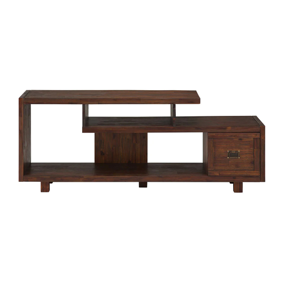
- Page 1 ASSEMBLY INSTRUCTIONS MONROE TV MEDIA STAND MODEL # AXCMON-08...
- Page 2 DO NOT RETURN FOR REPLACEMENT PARTS OR OTHER INQUIRIES PLEASE CONTACT US AT: 1-800-667-8992 PLEASE ENSURE TO HAVE THE COLLECTION NAME AND DESCRIPTION FROM THE PACKAGING OR INSTRUCTION BOOKLET...
- Page 3 IMPORTANT : Please read this manual carefully before beginning assembly of this product. Keep this manual for future reference. WARNING The maximum diagonal CRT television screen size is 25 inch to 27 inch (63.50 cm to 68.58 cm). For use with televisions weighing 220 lbs or less. Using larger or heavier televisions may cause instability or tip over which can lead to serious injury or even death.
-
Page 4: Safety Information
IMPORTANT : Please read this manual carefully before beginning assembly of this product. Keep this manual for future reference. SAFETY INFORMATION CAUTION: Injuries and damage can occur from furniture tip over if product is not properly anchored to the wall. Use the Furniture Anti-Tipping Restraint provided with the product. -
Page 5: Care And Maintenance
IMPORTANT : Keep this manual for future reference. CARE and MAINTENANCE Wood Furniture Care Perhaps the greatest environmental damage to wood furniture comes from wide swings in relative humidity (RH) in our homes. Wood absorbs and desorbs water as relative humidity rises and falls, and in doing so it swells and shrinks. -
Page 6: Pre-Assembly Information
PRE-ASSEMBLY INFORMATION MODEL # AXCMON-08 PART DESCRIPTION LEFT SIDE RIGHT SIDE QTY 1 QTY 1 QTY 1 MIDDLE BACK PANEL MIDDLE SHELF BOTTOM SHELF QTY 1 QTY 1 QTY 1 TOP DIVIDER BOTTOM DIVIDER BACK PANEL QTY 2 QTY 1 QTY 1 DRAWER QTY 1... -
Page 7: Hardware Description
PRE-ASSEMBLY INFORMATION MODEL # AXCMON-08 HARDWARE DESCRIPTION WOOD DOWEL ALLEN KEY SCREW M6 X 30mm ALLEN KEY Ø8 X 30mm QTY 30 QTY 1 QTY 18 PHILLIPS SCREW ROUND HEAD PHILLIPS SCREW CAM LOCK PIN M4 X 15mm M4 X 30mm CAM LOCK QTY 6 QTY 20 QTY 4 SETS... - Page 8 COMPONENTS-KEY DIAGRAM MODEL # AXCMON-08...
- Page 9 ASSEMBLY MODEL # AXCMON-08 STEP-1 1. Insert two Dowels 2 into drilled holes on Divider H . 2. Use rubber mallet to tap Dowels 2 into bottom of holes securely. 1/2 length of Dowels should be exposed. STEP-2 1. Align Wood Dowels on Bottom Divider H with drilled holes on Bottom Shelf E . 2.
- Page 10 ASSEMBLY MODEL # AXCMON-08 STEP-3 1. Insert two Dowels 2 into drilled holes on each side of Bottom Shelf E . 2. Use rubber mallet to tap Dowels 2 into bottom of holes securely. 1/2 length of Dowels should be exposed. 3.
- Page 11 ASSEMBLY MODEL # AXCMON-08 STEP-4 1. Insert four Dowels 2 into drilled holes on Middle Back Panel F . 2. Use rubber mallet to tap Dowels 2 into bottom of holes securely. 1/2 length of Dowels should be exposed. STEP-5 1.
- Page 12 ASSEMBLY MODEL # AXCMON-08 STEP-6 1. Insert two Dowels 2 into drilled holes on side of Shelf Panel D . 2. Use rubber mallet to tap Dowels 2 into bottom of holes securely. 1/2 length of Dowels should be exposed. 3.
- Page 13 ASSEMBLY MODEL # AXCMON-08 STEP-7 1. Align Wood Dowels on Middle Back Panel F with drilled holes on Middle Shelf D . 2. Align Cam Lock Pins with drilled holes and attach Middle Back Panel F . 3. Insert two Cam Locks 6 into drilled holes on Middle Back Panel F . 4.
- Page 14 ASSEMBLY MODEL # AXCMON-08 STEP-8 1. Insert two Dowels 2 into drilled holes on each Top Divider G . 2. Use rubber mallet to tap Dowels 2 into bottom of holes securely. 1/2 length of Dowels should be exposed. STEP-9...
- Page 15 ASSEMBLY MODEL # AXCMON-08 STEP-10 1. Insert two Dowels 2 into drilled holes on Top C . 2. Use rubber mallet to tap Dowels 2 into bottom of holes securely. 1/2 length of Dowels should be exposed. STEP-11 1. Attach Top C to Dividers G using six Allen Key Screws 1 (three Allen Key Screws / each Divider G ).
- Page 16 ASSEMBLY MODEL # AXCMON-08 STEP-12...
- Page 17 ASSEMBLY MODEL # AXCMON-08 STEP-13 NOTE: The screwdriver is not included in the hardware pack. 1. Attach the Back Panel I to back frame by using six Phillips Screws Round Head 4 . 2. Use Phillips screwdriver to tighten screws.
- Page 18 ASSEMBLY MODEL # AXCMON-08 STEP-14 NOTE: The screwdriver is not included in the hardware pack. 1. Attach the Legs K and Leg L to underneath of Bottom Shelf E by using four Phillips Screws 5 for each Leg. 2. Use Phillips screwdriver to tighten screws.
- Page 19 ASSEMBLY MODEL # AXCMON-08 STEP-15 1. Insert assembled drawer J into glides on assembled TV. Note: Levelers on bottom of legs can be adjusted if floor is uneven.
- Page 20 FURNITURE TIP OVER RESTRAINT ASSEMBLY WARNING Serious or fatal crushing injuries can occur from furniture tip-over. If the furniture tip over restraint kit is not in the box, please contact our customer service department in order to obtain another kit before using the furniture. STEP-16 NOTE: The screwdriver is not included in the hardware pack.
- Page 21 FURNITURE TIP OVER RESTRAINT ASSEMBLY Furniture Tip Over Restraint Instructions: Attach one of the mounting brackets securely to the back edge of the furniture. Use the shorter screw. Determine where furniture is to be placed and mark location on the wall for mounting bracket screw hole approximately 2 inches below the bracket mounted to the furniture.
Need help?
Do you have a question about the MONROE and is the answer not in the manual?
Questions and answers