Advertisement
Quick Links
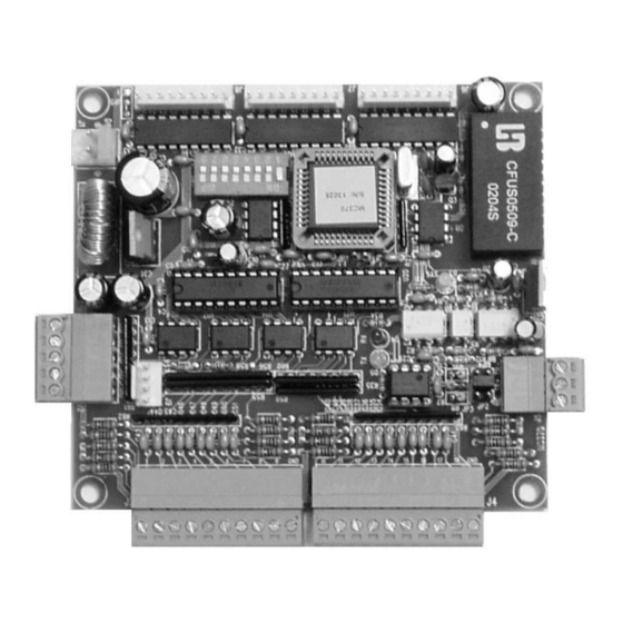
MC370 INPUT/OUTPUT BOARD
MC370 INPUT/OUTPUT BOARD
Features
On board opto-isolated RS485 interface.
4 Analog Inputs(0~4.095V, 10BITS)
24 on-board output drivers
18 Inputs with line fault detect
8 K EEPROM
Support i-Control System
Support Easy Control
Provide ActiveX Control for your application software.
User's Manual
DEVICE CODE: 370
www.easy-controls.com
1
Advertisement

Related Manuals for Easy Controls MC370

Summary of Contents for Easy Controls MC370
- Page 1 MC370 INPUT/OUTPUT BOARD MC370 INPUT/OUTPUT BOARD Features On board opto-isolated RS485 interface. 4 Analog Inputs(0~4.095V, 10BITS) 24 on-board output drivers 18 Inputs with line fault detect 8 K EEPROM Support i-Control System ...
- Page 2 MC370 INPUT/OUTPUT BOARD IMPORTANT Although the information contained herein has been carefully verified, NEWELL TECHNOLOGIES LIMITED assumes no responsibility for any errors that may occur, for any damage to property or persons resulting from improper use of this manual or from the related software. NEWELL TECHNOLOGIES LIMITED products are not authorized for use as components in medical, life support or military devices.
- Page 3 MC370 INPUT/OUTPUT BOARD Document Overview Connectors ................................ 4 PCB Size ................................5 Technical Specifications............................. 5 Power Supply (J1) ............................. 6 Reset.................................. 6 Communication Interface (J4, JP2, JP3, JP4)....................6 Analog Inputs(J2)............................... 6 Input Connection (J3, J4)........................... 6 Output Connector (J6, J7, J8) ........................... 7 Device ID (SW1) ..............................
- Page 4 MC370 INPUT/OUTPUT BOARD Connectors Output Connector J6, J7, J8 Power Supply Device ID System Status LED System Startup Delay Jumper JP1 Analog Input J2 RS485 Settings: JP2 pull-on resistance JP4 pull-down resistance Communication Status LED JP3 termination resistance COMMON (GND)
-
Page 5: Technical Specifications
MC370 INPUT/OUTPUT BOARD PCB Size 100mm φ4.5mm 7.5mm 110mm Technical Specifications Maximum boards 256(addressed by device ID) (In same control network) more than 256 (addressed by serial number) Communication Interface RS485 Analog Input 4(0~4.095v, 10bits) 18, With line fault detect... - Page 6 MC370 INPUT/OUTPUT BOARD Power Supply (J1) Connectors The device requests an DC power supply and connect to J1. Please refer to DC: 8 - 30 V 5W Reset The device reset and set default output state at power-up, the state of the outputs does not change even a system software or hardware reset (Watchdog Timer - WDT) may occur.
- Page 7 MC370 INPUT/OUTPUT BOARD the value of ach input has two resisters(R1 & R2) installed, the precision is 1%, refer to the diagram below, the resister can be configured by software. Connector: J3, J4. Please refer to Connectors. Note: All COMMON are connected to Ground of the device.
- Page 8 MC370 INPUT/OUTPUT BOARD Device ID (SW1) Your application software may use device ID to seek and control the device, this means you must assign uniquely identifies for same devices in the same control network, and the device ID can be 0 to 255.
-
Page 9: Customer Service
MC370 INPUT/OUTPUT BOARD Easy Control Resource Please install software [Easy Control]. To download the newest version, you can go to http://www.easy-controls.com/download/ Properties Settings Choose the menu [Device] - [Properties] to open the dialog window and press button [Help] to get the detail of the settings.
Need help?
Do you have a question about the MC370 and is the answer not in the manual?
Questions and answers