Table of Contents
Advertisement
Quick Links
IF YOU CANNOT READ OR UNDERSTAND THESE INSTALLATION
NOTE:
feature for any length of time, then the handheld/wall mount, receiver/control module and application should be in the
"OFF" position.
INTRODUCTION
This remote control system was developed to provide a safe, reliable and user-friendly remote control system for gas
heating appliances. It has a built-in thermostat. This all battery system operates independently of household current.
The system operates on radio frequencies with a non-directional signals. The systems operating range is approximately
20-feet. The system operates on one of 1,048,576 security codes that are programmed into the transmitter at the factory;
the remote receiver's code must be matched to that of the transmitter prior to initial use. It is designed to be used with
millivolt gas valves as a dry contact switch.
f i r e - p a r t s . c o m
Review COMMUNICATION SAFETY SECTION under TRANSMITTER section. These signal/temperature
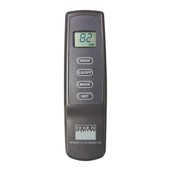
TRANSMITTER
ON
BUTTON
ON
OFF
MODE
OFF
BUTTON
SET
COMPARTMENT
FRONT
BUTTON SETTINGS
1. ON - - -
Turns appliance ON
2. OFF - -
Turns appliance OFF
3. MODE
Cycles control between manual and thermo mode.
4. SET --
Sets temperature in thermo mode.
-
Robert H Peterson Co. Model: RR-2A
Model: RR-2A
INSTALLATION AND OPERATING INSTRUCTIONS
INSTRUCTIONS DO NOT ATTEMPT TO INSTALL OR OPERATE
WALL CLIP
SLOT
MODE
BUTTON
SET
BUTTON
BATTERY
BACK
This remote control SYSTEM offers the user a battery-operated remote
control that operates most millivolt gas valves used in some heater rated
The transmitter operates on (2) 1.5V AAA batteries.
It is recommended that ALKALINE batteries always be used for longer
battery life and maximum operational performance.
Before using the transmitter, install the (2) AAA transmitter batteries into
the battery compartment. (Use caution that batteries are installed in the
proper direction)
ON
OFF
MODE
SET
1
2
3
4
9-2-20 Page 1
Advertisement
Table of Contents

Related Manuals for RealFyre RR-2A


Summary of Contents for RealFyre RR-2A
- Page 1 1. ON - - - Turns appliance ON 2. OFF - - Turns appliance OFF 3. MODE Cycles control between manual and thermo mode. 4. SET -- Sets temperature in thermo mode. Robert H Peterson Co. Model: RR-2A 9-2-20 Page 1...
-
Page 2: Manual Function
THERMO SET Release the SET button at desired temperature. The LCD screen will display the set temperature for 3 seconds and the LCD screen will default to display the room temperature. 9-2-20 Page 2 Robert H Peterson Co. Model: RR-2A... -
Page 3: Operational Notes
Control System is operating. DO NOT program or thermostatically set this Control to operate a hearth appliance burning unattended; it may cause damage or serious injury. If an Adult is going to be away from the hearth appliance or “OFF” position. Robert H Peterson Co. Model: RR-2A 9-2-20 Page 3... -
Page 4: Installation
Push the white slide button over the receiver slide switch only after making sure the Remote Receiver remote receiver has LEARNED the transmitter’s security code (see LEARNING TRANSMITTER TO RECEIVER). 9-2-20 Page 4 Robert H Peterson Co. Model: RR-2A... -
Page 5: Wiring Instructions
Connect another wire (not included) 24VAC between the other receiver wire terminal and the TH (thermostat) terminal on the ELECTRONIC REMOTE RECEIVER hot wire MODULE. 120VAC Robert H Peterson Co. Model: RR-2A 9-2-20 Page 5... -
Page 6: System Check
MODE. Engaging the “LOCK-OUT” prevents only the manual operation of the TRANSMITTER. If in the auto modes, the THERMO operation will continue to operate normally. To totally “LOCK-OUT” the operation of the TRANSMITTER’S operating signals; the transmitter’s MODE must be set to OFF. 9-2-20 Page 6 Robert H Peterson Co. Model: RR-2A... - Page 7 The transmitter can be hung on a wall using the clip provided. If the clip is WALL CLIP installed on a solid wood wall, drill 1/8” pilot holes and install with the screws with the wall; then install the screws provided. BATTERY COMPARTMENT Robert H Peterson Co. Model: RR-2A 9-2-20 Page 7...
-
Page 8: Fcc Requirements
Remote Receiver 6V - 4 ea. AA 1.5 Alkaline FCC ID No.’s: transmitter - K9LSP1001TH; receiver - K9L330IRX Operating Frequency: 303.8 MHZ Canadian IC ID No.’s: transmitter – 2439A-SP1001TH; receiver – 2439A-3301RX 9-2-20 Page 8 Robert H Peterson Co. Model: RR-2A... - Page 9 RR-1B / RR-2A REMOTE SYSTEMS ADDENDUM WIRING TO AN EXISTING TOGGLE SWITCH 1. Locate the electrical connectors on the back of the toggle switch that controls your gas log set. 2. Remove the two (2) spare female connectors (if installed) from the two (2) male piggyback connectors. The piggy- back connectors are each a part of a female electrical connector wired to burner control valve (Fig.
Need help?
Do you have a question about the RR-2A and is the answer not in the manual?
Questions and answers