Table of Contents
Advertisement
Quick Links
INSTALLATION AND OPERATING INSTRUCTIONS
FOR OPERATING SERVO MOTOR VALVE, MANUALLY AND WITH A THERMOSTAT FUNCTION
IF YOU CANNOT READ OR UNDERSTAND THESE INSTALLATION INSTRUCTIONS
NOTE:
then the handheld/wall mount, receiver/control module and application should be in the "OFF" position.
INTRODUCTION
This remote control system was developed to provide a safe, reliable, and user-friendly remote control system for gas
heating appliances. The system operates on radio frequencies (RF) within a 20-foot range using non-directional signals.
The system operates on one of 1,048,576 security codes that are programmed into the transmitter at the factory; the
Remote Receiver's code must be matched to that of the transmitter prior to initial use
f i r e - p a r t s . c o m
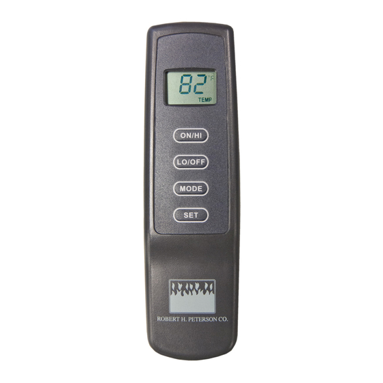
TRANSMITTER
ON/HI
BUTTON
ON/HI
LO/OFF
MODE
LO/OFF
BUTTON
SET
F
R
O
N
T
ON/HI
LO/OFF
MODE
SET
Robert H Peterson Co. Model: VR-2A
MODEL: VR-2A
MULTI-FUNCTION WIRELESS REMOTE CONTROL SYSTEM
DO NOT ATTEMPT TO INSTALL OR OPERATE
WALL CLIP
SLOT
MODE
BUTTON
SET
BUTTON
BATTERY
COMPARTMENT
B
A
C
K
1
KEY SETTINGS
2
•
ON/HI
•
LO/OFF
3
•
MODE
•
SET
4
This remote control SYSTEM offers the user a battery-operated
remote control to power up to a 6 VDC servo motor or solenoid such
as those used with gas valves used in some heater rated gas logs,
The servo motor or solenoid circuit uses the battery power from
the receiver to operate a servo motor or solenoid. The circuit has
reversing polarity software which reverses the positive (+) and
negative (-) output of the receiver's battery power to drive the servo
motor forward/backward. (HI/LO FLAME) The SYSTEM is controlled
by the remote transmitter.
The transmitter operates with two (2) 1.5V AAA batteries.
It is recommended that ALKALINE batteries always be used for
longer battery life and maximum operational performance.
Before using the transmitter, install the (2) AAA transmitter batteries
into the battery compartment. (Use caution that batteries are
installed in the proper direction)
- Operates unit to ON position, Manually operated servo HI.
- Operates unit to OFF position, manually operated servo LO.
- Changes unit from manual mode to thermo mode.
- Sets temperature in thermo mode.
.
9-9-20 Page 1
-
Advertisement
Table of Contents

Related Manuals for RealFyre VR-2A


Summary of Contents for RealFyre VR-2A
- Page 1 • LO/OFF - Operates unit to OFF position, manually operated servo LO. MODE • MODE - Changes unit from manual mode to thermo mode. • - Sets temperature in thermo mode. Robert H Peterson Co. Model: VR-2A 9-9-20 Page 1...
- Page 2 45° to 99° then restart over at 45° ) Next release the SET key. The LCD screen set temperature for 3 seconds, then the LCD screen will default to display the room temperature. Robert H Peterson Co. Model: VR-2A 9-9-20 Page 2...
- Page 3 3-position slide button on the remote receiver is in the REMOTE position. The remote receiver houses the microprocessor that responds to commands from the transmitter to control system Frequency adjusting operation. Remote Receiver access hole Robert H Peterson Co. Model: VR-2A 9-9-20 Page 3...
- Page 4 3/16” female terminal and wire may need to be cut to a shorter length. This can be done by removing the (2) wires from the receiver cutting them to the desired length then reinstalling them into the same connections on the receiver. Robert H Peterson Co. Model: VR-2A 9-9-20 Page 4...
- Page 5 MODE. Engaging the “LOCK-OUT” prevents only the manual operation of the TRANSMITTER. If in the auto modes, the THERMO operation will continue to operate normally. To totally “LOCK-OUT” the operation of the TRANSMITTER’S operating signals; the transmitter’s MODE must be set to OFF. Robert H Peterson Co. Model: VR-2A 9-9-20 Page 5...
- Page 6 REMOTE position. Press the learn button and release after 10 seconds. You should hear three (3) long audible beeps indicating all codes have cleared. You can now “learn” the transmitter to the receiver as described in the General Information Section. Robert H Peterson Co. Model: VR-2A 9-9-20 Page 6...
- Page 7 SPECIFICATIONS BATTERIES: Transmitter 12V - (A23); Remote Receiver 6V - 4 ea. AA 1.5 Alkaline FCC ID No.'s: transmitter - K9LSP1001TH Operating Frequency: 303.8 MHZ Canadian ISC ID No.'s: transmitter -2439A-SP1001TH Robert H Peterson Co. Model: VR-2A 9-9-20 Page 7...
Need help?
Do you have a question about the VR-2A and is the answer not in the manual?
Questions and answers