Table of Contents
Advertisement
Quick Links
KENCO ENGINEERING COMPANY
P.O. BOX 470426 TULSA, OK 74147-0426 ● PHONE: (918) 663-4406 FAX: (918) 663-4406
GENERAL DESCRIPTION
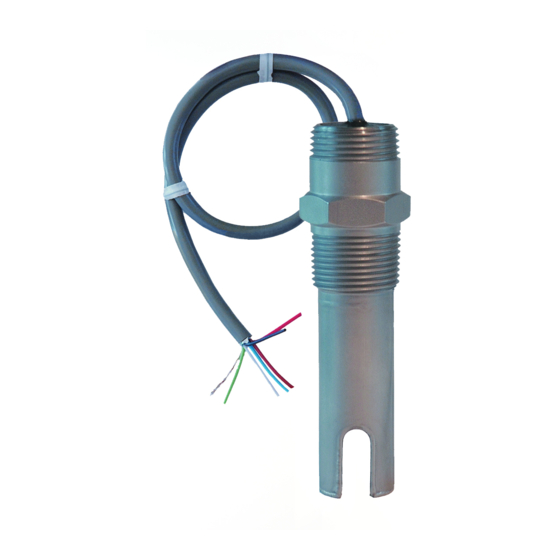
The KUSO Series Ultrasonic Level Switches are ideal, low cost solutions for many liquid level control applications. They
operate in a wide variety of services.
PRINCIPLE OF OPERATION
Ultrasonic switches use piezoelectric crystals to transform electrical energy into mechanical motion (sound). The
Transmit Crystal sends a pulse of sound through the space between the crystals, to the Receive Crystal. If the space is
filled with air, gas, or vacuum, the Receive Crystal does not detect the sound pulse. However, if the space is filled with
liquid, any liquid, the pulse is detected by the Receive Crystal, and the switch output changes.
MODEL DESCRIPTION
Style
Cable Length
*(In Feet)
*Standard is 1FT.
INSTALLATION
Unpack the switch carefully. Inspect all units for damage. Report any damage to carrier immediately. Check the
contents against the packing slip and purchase order.
Kenco's Ultrasonic Switches are manufactured to the highest quality standards. These switches use electronic
components that can be damaged by static electricity. Make sure that you are properly grounded before starting
installation. Insure that all electrical connections are properly made, and that there are no "floating" connections.
Operational Check
Before installing the switch a simple operational check should be performed, as follows:
1. Fill a container with water
2. Connect the wiring (see the section on "Wiring")
3. Apply power
4. Place the sensor gap into the water.
a. Relay Version -- The relay will energize (the contacts between (NC) and (C) should open).
b. 2-wire Version -- The current in the Red wire will be 16.0mA ±1.0mA.
5. Remove the sensor from the liquid.
a. Relay Version – The relay will de-energize (the contacts between (NC) and (C) should close)
b. 2-wire Version – The current in the Red wire will be 4.0mA ± 1.0mA.
6. Disconnect the wiring
Mounting
For threaded process connections, screw sensor into the opening using a wrench on the sensor mounting nut flats. Use
thread tape or suitable pipe compound on the threads. If flanged, bolt the sensor to the mating flange with the proper
gasket.
The sensor gap must protrude into the vessel / pipe being measured. The sensor will not function properly if the detection
tip is in a nozzle.
www.kenco-eng.com e-mail: info@kenco-eng.com
MODEL KUSO ULTRASONIC SWITCH
INSTALLATION / OPERATION INSTRUCTIONS
KUSO -
-
Style
Description
1A SPDT 316LSS
Code
0
Advertisement
Table of Contents

Related Manuals for Kenco KUSO


Summary of Contents for Kenco KUSO
- Page 1 MODEL KUSO ULTRASONIC SWITCH INSTALLATION / OPERATION INSTRUCTIONS GENERAL DESCRIPTION The KUSO Series Ultrasonic Level Switches are ideal, low cost solutions for many liquid level control applications. They operate in a wide variety of services. PRINCIPLE OF OPERATION Ultrasonic switches use piezoelectric crystals to transform electrical energy into mechanical motion (sound). The Transmit Crystal sends a pulse of sound through the space between the crystals, to the Receive Crystal.
- Page 2 Wiring It is recommended that conduit be installed onto the ¾” NPT connection on the back of the sensor. A seal drain fitting should be used to prevent moisture from entering the switch. All wiring, conduit, and electrical fittings must conform to local electrical codes for the location selected.
Need help?
Do you have a question about the KUSO and is the answer not in the manual?
Questions and answers