
Related Manuals for Hillrom Helion Main Unit R

Summary of Contents for Hillrom Helion Main Unit R
- Page 1 Instructions for use Helion Video Management System Read the instructions for use carefully prior to using the ENGLISH product and keep them safe for future reference. en-GB...
- Page 2 This page is intentionally left blank.
- Page 3 Language ID: Version: Material number: 774259 Publication date: 2021-09-01 This document applies to the following units sold: Product designation Helion Main Unit R VR401111-1 Helion Main Unit VR401111-1ND Helion Main Unit RD VR401111-1D Helion Main Unit RSD VR401111-1DT Helion Main Unit RS...
- Page 4 Helion VIDEOMED S.r.l. waives any liability for improper use of the system and/or for damage caused as a result of operations not covered by the technical documentation. 80028681_002_C – 774259 – 2021-09-01...
- Page 5 Helion PREFACE All rights reserved. No part of this publication may be copied, distributed, translated into other languages or transmitted by any electronic or mechanical means, including photocopying, recording or any other storage and retrieval system, for other purposes that are not exclusively the buyer’s personal use, without the manufacturer’s express written permission.
- Page 6 Helion This page is intentionally left blank. 80028681_002_C – 774259 – 2021-09-01...
-
Page 7: Table Of Contents
Contents Contents System identification ............9 Identification plates . - Page 8 Contents 6.3.4.5 Enable camera setting (Preset) ..........51 “Recording”...
-
Page 9: System Identification
A H F I N K E O J E D J C J L K K A F K Helion Main Unit R A L C J N D F C L I K D L D D F J L N K... - Page 10 35010 Limena, Italy 2021-08-11 Made In Italy E464244 hillrom.co.uk INPUT: 100-240V~1.1-2.0A 50/60 Hz FUSES RATING: 2X 250VAC - T3.15A A L G O A O A I B K H I A L F N C J D K A H F I N K E O J E D I C I J P J N E K...
- Page 11 35010 Limena, Italy 2021-08-11 Made In Italy E464244 hillrom.co.uk INPUT: 100-240V~0.2-0.48A 50/60 Hz FUSES RATING: 2X 250VAC - T1.6A A L G O A O A I B K H K A L F N C J D K A H F I N K E O J A D J D J L D O O F K...
-
Page 12: Reference Standards
System identification Reference standards VIDEOMED S.r.l. declares that the Helion Video Management System complies with the specific standards of the medical sector. Legislation and rules applicable to the United States of America (USA): Standard Description 21 CFR Part 820 Quality System Regulation 21 CFR Part 821 Medical Device Tracking Requirements 21 CFR Part 803, 806, 807... -
Page 13: Warranty
System identification Legislation and rules applicable to European Union (EU) countries: Standard Description Regulation (EU) 2017/745 The regulation on medical devices amending Directive 93/42/ EEC will enter into force on 26 May 2021 93/42/EEC Medical Devices Directive (MDD) and f.m. 2007/47/EC EN 1041:2008 Information supplied by the manufacturer of medical devices EN ISO 13485:2016... -
Page 14: General Preliminary Information
General preliminary information General preliminary information Recipients of the instructions for use The instructions for use of the Helion Video Management System are intended for operators trained and authorised to operate it. Operator training must be documented. The instructions for use contain topics referring to correct use of the system, so as to keep its functional and qualitative characteristics unchanged over time. -
Page 15: Personnel Qualifications
General preliminary information Personnel qualifications Consult the following table in order to establish personnel skills and qualifications: Qualification Description Operator Natural or legal person (for example, a doctor or a hospital) who owns and uses the Helion Video Management System. They must provide a safe system and adequately instruct the user in the intended and permitted use of the system. - Page 16 AMD 1 (2012), CAN/CSA-C22.2 No. 60601-1 (2014) Consult instructions for use (IFU). A copy of the IFU is available on this website. A printed copy of the IFU can be ordered from Hillrom for delivery within 7 calendar days. hillrom.co.uk 80028681_002_C – 774259 – 2021-09-01...
-
Page 17: Safety Information
Safety information Safety information General safety warnings The Helion Video Management System must be used by suitably trained personnel. DANGER ELECTRIC SHOCK FROM DAMAGED MAINS POWER CABLE! Check the mains power cable before connecting it and do not use it if it has been crushed or the insulation is damaged. DANGER ELECTRIC SHOCK FROM PRESENCE OF EXPOSED LIVE PARTS! It is also recommended to periodically check the integrity of the... -
Page 18: Electromagnetic Compatibility
Safety information CAUTION COMPULSORY MEASUREMENT OF DISPERSAL CURRENTS It is necessary to measure leakage currents with circuits downstream of the Helion system open. Otherwise, the leakage currents of these circuits will be added to those of the Helion system. Electromagnetic compatibility The Helion Video Management System supplied contains electronic components subject to Electromagnetic Compatibility regulations, which are affected by conducted and radiated... - Page 19 Safety information Guidance and manufacturer's declaration - Electromagnetic immunity The product is suitable for use in a specific electromagnetic environment. The customer and / or user of the product must ensure that it is used in an electromagnetic environment as described below: Immunity test IEC test level Compliance...
-
Page 20: Useful Life Of The System
Safety information Guidance and manufacturer's declaration - Range and frequency level: RF wireless communication equipment Test frequency Modulation Minimum immunity Applied immunity (MHz) level (V / m) level (V / m) ** Pulse modulation: 18 Hz * FM + 5 Hz deviation: 1 kHz sine ... -
Page 21: Cleaning
Safety information Cleaning CAUTION Do not use any cleaning products. This paragraph describes how to clean the Helion system. Cleaning shall be performed on a regular basis (at least once a week) to ensure components remain intact and in good working order. -
Page 22: System Description
System description System description Intended use The Helion Video Management System is a medical video communication system used exclusively to display and manage existing audio-video sources, and to control an operating light within the specifications established by the manufacturer. The intended use requires the following: –... -
Page 23: Reasonably Foreseeable Misuse
System description Reasonably foreseeable misuse Cases of reasonably foreseeable misuse, which are strictly prohibited, are listed below: – using the system in areas at risk of explosion; – using the system near strong electromagnetic fields; – using the system in a different way to what is required in paragraph “Intended use”. -
Page 24: Obligations And Prohibitions
System description Obligations and prohibitions The VIDEOMED Helion system must only be used by medical and paramedical personnel with the requisite professional qualifications, who have read these instructions for use and have been adequately trained in the use of the system. The training is certified through participation in the training course entitled “training for healthcare personnel in the use of Helion”. -
Page 25: Technical Data
System description Technical data Main unit - Technical Specs Video inputs 18 (14 DVI, 2 3G-SDI, 2 CVBS) Monitor outputs 10 DVI over CAT6/7 or optic fibre Supported resolutions Standard video PAL (720 x 576) HDTV (1280 x 720) Full HDTV (1920 x 1080p) PC resolution (1024 x 768, 1280 x 1024, 1600 x 1200, 1920 x 1200) UHD / 4K option with 4K unit Dimensions... - Page 26 System description Conference unit - Technical Specs Standard video H.263, H.263+, H.263++, H.264, H.264 High Profile, H.264 SVC. Encoding up to 1920 x 1080p 60fps Video inputs 2 inputs: – 2 x HD video in (1080p60/720p60) Dimensions 44 x 430 x 450 mm Power supply 100-240 V 50-60Hz AC Video outputs...
- Page 27 System description 4K Unit - Technical Specs Video inputs 5 HDMI ports Video outputs 5 HDMI ports Supported resolutions Up to 4096 x 2160 at 60Hz Transmission To Optic fibre cabling Monitor Additional ports 5 x DVI over CAT 6/7 output scaled to FullHD 1080 5 x DVI over CAT 6/7 pass-through input (FullHD 1080) Dimensions 44 x 430 x 450 mm...
- Page 28 System description 4K Plus unit - Technical Specs Video inputs 2 HDMI ports 2 display port Video outputs 2 HDMI ports 2 display port Supported resolutions Up to 4096 x 2160 at 60Hz Transmission To Optic fibre cabling Monitor Additional ports 4 x DVI over CAT6/7 output scaled to FullHD 1080 4 x DVI over CAT6/7 pass-through input (FullHD 1080) Dimensions...
- Page 29 System description Rack unit - Technical Specs Dimensions 800 x 600 x 757 mm Colour RAL 7016 puckered Environmental Operating temperature: +10/+40 °C conditions Operating relative humidity range: 30% to 75% Operating atmospheric pressure range: 70.0 kPa to 106.0 kPa Storage temperature: -40/+70 °C Storage relative humidity range: 10% to 100%, including condensation...
-
Page 30: Measurement And Weight Layout
System description Measurement and weight layout Main unit Dimensions 133 x 430 x 450 mm Unit weight 13.5 kg Rack dimensions (optional) Rack Dimensions (optional) Rack brackets (optional) Rack Brackets (optional) 80028681_002_C – 774259 – 2021-09-01... - Page 31 System description Conference unit Dimensions 44 x 430 x 450 mm Unit weight 8 kg Rack dimensions (optional) Rack Dimensions (optional) Rack brackets (optional) Rack Brackets (optional) 80028681_002_C – 774259 – 2021-09-01...
- Page 32 System description 4K Unit Dimensions 44 x 430 x 450 mm Unit weight 5.5 kg Rack dimensions (optional) Rack Dimensions (optional) Rack brackets (optional) Rack Brackets (optional) 80028681_002_C – 774259 – 2021-09-01...
- Page 33 System description 4K Plus unit Dimensions 44 x 430 x 450 mm Unit weight 5.5 kg Rack dimensions (optional) Rack Dimensions (optional) Rack brackets (optional) Rack Brackets (optional) 80028681_002_C – 774259 – 2021-09-01...
- Page 34 System description Rack unit Dimensions 800 x 600 x 757 mm Unit weight 64 kg ADJUSTABLE FOOT HEIGHT Adjustable foot height 80028681_002_C – 774259 – 2021-09-01...
-
Page 35: System Components
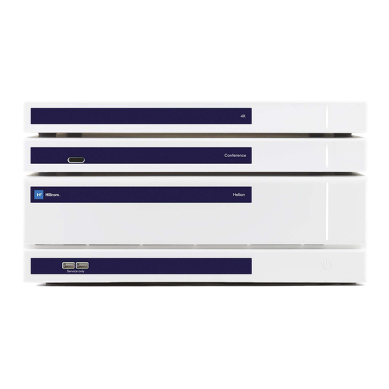
System description System components The Helion Video Management System has a modular structure composed of 3 operating units that can be used simultaneously. The only unit that can operate independently is the Main unit. Main unit Conference unit 4K Unit or 4K Plus unit 4.7.1 Main unit The following functions are available via the Main unit. -
Page 36: Conference Unit
System description 4.7.2 Conference unit The Conference unit is equipped with Full HD video conference technology that allows the exchange of information in video conference with the operating theatre by sharing high resolution images and videos outside the room. The following connection ports can be found on the back of the unit. -
Page 37: Control Software
System description 4.7.5 Control software The management software of the Helion Video Management System makes it possible to control and manage each functional unit. A lower selection bar (always visible) allows the software sections to be uniquely identified based on the function performed. The sections of the selection bar are described below: Function Description... -
Page 38: Operation
Operation Operation First system start The Helion Video Management System is delivered to the operator by authorised installation technical personnel from VIDEOMED S.r.l. System commissioning requires the operator to be adequately trained in the functional and visual controls, adjustments and calibration, cleaning and maintenance of the system, and also in the applicable user instructions. -
Page 39: Connection To Sources
Operation Connection to sources When a new video source is connected to the system, a dynamic Preview (frame) is displayed in the Source List, showing the name of the socket/line used. The Preview updates periodically as long as the signal remains active. -
Page 40: System Start-Up/Shutdown By Remote Button
Operation System start-up/shutdown by remote button The Helion Video Management System allows units to be restarted via a remote on/off button installed inside the operating theatre (typically on a pendant panel or wall unit). Using this solution, the operator can manage the entire video management system without needing to access the Technical rack. -
Page 41: User Interface
User Interface User Interface General description of the user interface The user interface is divided up as follows: Element Description Status bar It contains important information such as the patient's name and the number of recorded media related to them. Information such as the date, time and a dashboard showing the status of the recording, video conference, streaming and advanced modes “Privacy Mode”, “Do Not Disturb”... -
Page 42: Control Touchscreen
User Interface Control touchscreen The control screen is a high-resolution touchscreen. The user interface buttons are activated by a brief touch of the finger, or by swiping. The control screen has its own setup menu to access the monitor settings: –... - Page 43 User Interface The main Video Routing screen is divided as follows: list of sources connected list of monitors enabled To send a video signal to a monitor, drag the relevant image from the Source List [A] available and drop it into one of the enabled monitors [B] by drag&drop.
-
Page 44: Live Preview
User Interface 6.3.1 Live Preview With the Live Preview function, it is possible to enlarge or reduce the preview of the video signal of each connected source. If the preview is enlarged, it will only appear momentarily on the screen. To display the Live Preview of one of the signals available in the Source list, proceed as follows: Step... - Page 45 User Interface The following icons are present in the Live Preview window: Icon Function Makes it possible to start/stop recording of the displayed signal. If the icon is grey, this indicates that the function is not active. To activate the function, it is necessary to select a patient from the list (refer to the paragraph “Selecting a patient in the list”).
-
Page 46: Quick Access - Recording
User Interface 6.3.2 Quick Access - Recording It is possible to use a quick activation system directly from the Video Routing screen to start recording. A dedicated Recording screen is available to access advanced functions. A dedicated Recording function enables recording. In any case, it is possible to use an additional quick activation system from the Video Routing function. -
Page 47: Quick Access - Streaming
User Interface 6.3.3 Quick Access - Streaming To activate streaming, proceed as follows: Step Image Press the icon of a Preview to start streaming the signal from one of the connected sources. When streaming is active, the button is in a white background in the icon of the selected source and is disabled in the Previews of the remaining... -
Page 48: Ptz Camera Control
User Interface 6.3.4 Ptz camera control If activated on a controllable camera signal, the Live Preview function will allow access to its movement controls. 6.3.4.1 Roomcam zoom adjustment To adjust the zoom of the Roomcam, proceed as follows: Step Image to adjust the zoom to obtain the desired image (view). -
Page 49: Save Camera Setting (Preset)
User Interface 6.3.4.3 Save camera setting (Preset) To save a specific video camera setting (Preset), proceed as follows: Step Image After the video camera has been adjusted to the desired position, press Enter the name to be assigned and press to confirm. -
Page 50: Delete Camera Setting (Preset)
User Interface 6.3.4.4 Delete camera setting (Preset) To delete a video camera setting from the Preset list, proceed as follows: Step Image Press Press and hold the button until it is deleted. 80028681_002_C – 774259 – 2021-09-01... -
Page 51: Enable Camera Setting (Preset)
User Interface 6.3.4.5 Enable camera setting (Preset) To activate a video camera Preset, proceed as follows: Step Image Press the desired Preset in the list. Press to confirm the Preset selection. “Recording” function The Recording function makes it possible to capture snapshots and record video from the signals connected to the system. - Page 52 User Interface The main Recording screen is divided as follows: source list view of the two recording channels list of screenshots and videos stored The user may view and reproduce any material stored during the surgical activity (images and video) at any time by pressing the icon .
-
Page 53: Image Data Post-Processing
User Interface 6.4.1 Image data post-processing By using locally stored data, it is possible to: – create video sequences from screenshots saved during the operation (MATS - Movie Around The Snap), – create still images generated from previously recorded video, –... -
Page 54: Recording
User Interface Channel selection and recording will in no way affect the signals sent to the monitors via Video Routing. It is not possible to start recording if a reference patient is not present. 6.4.3 Recording To record from the Recording function, proceed as follows: Step Image Press the... -
Page 55: Snapshot And Video Playback
User Interface 6.4.4 Snapshot and video playback To play snapshots and videos, proceed as follows: Step Image Press to view all images and videos related to the selected patient. Press the icon to enlarge the individual media item. A new window appears which, depending on the file selected (image or video), allows you to: Icon... -
Page 56: Cutting Video
User Interface 6.4.5 Cutting video To cut videos, proceed as follows: Step Image Press to view all images and videos related to the selected patient. Press the icon to enlarge the single item. Press the icon. A cursor appears on the progress bar. - Page 57 User Interface Step Image Once the cutting points have been determined, extract the portion of the video by pressing A new video appears in the photo/video list for the same patient. 80028681_002_C – 774259 – 2021-09-01...
-
Page 58: Export Images And Videos
User Interface 6.4.6 Export images and videos Click on the icon to access the folder for storing images and videos for the selected patient. This step must be performed to close the patient file and export the files. A screen is displayed with all the captured images and videos. The following icons are available in the Export window: Icon Function... - Page 59 User Interface Step Image Press (on the right side of the screen) to send the files to the selected destinations. By pressing , the files are sent to the selected destinations and the patient's session is deleted. Activation of each of the export options shown above depends on settings that need to be authorised and guided by the hospital’s IT managers.
-
Page 60: Delete Images And Videos
User Interface 6.4.7 Delete images and videos Click on the icon to access the folder for storing images and videos for the selected patient. To delete images and videos, proceed as follows: Step Image Select the videos or images you wish to delete by clicking directly on their thumbnails. -
Page 61: Video Conference" Function
User Interface “Video Conference” function The Video Conference function allows video conferencing in a two-way audio and video connection from the operating theatre to external rooms: – external participants located in other rooms or areas of the building are connected to the device via LAN connection, –... -
Page 62: Selecting The Signals To Be Sent By Video Conference
User Interface The main Video Conference screen is divided as follows: source list view of the two video conference channels When the video conference is active, the dashboard receiver icon turns green 6.5.1 Selecting the signals to be sent by video conference From the Source List, drag the source you wish to send via video conference in the Primary Channel (or Secondary Channel) box. -
Page 63: Removing The Signals To Be Sent By Video Conference
User Interface 6.5.2 Removing the signals to be sent by video conference Press one of the boxes related to the primary and/or secondary video conference channel and then the icon to be shown inside it to remove the video signal from the video conference. The thus removed video signal will no longer be shared with video conference participants. -
Page 64: Call Recipient Selection
User Interface 6.5.3 Call recipient selection To select the call recipient, press the relevant icon (depending on the mode) on the right side of the screen. The icons are described below: Icon Description Image Enables selection of a name from the contact list. Enables selection of a name/address from those indicated in the calls sent/... -
Page 65: Call Start
User Interface 6.5.4 Call start Once the call recipient has been selected, the call can be started. To start the call, proceed as follows: Step Image Press the green call button The call button turns red indicate the option to end the call. -
Page 66: Patient Data Management
User Interface 6.6.1 Patient data management Press the icon on the side menu to access patient data management. On the screen displayed, after pressing the icon, the list of patients [A], already entered and divided between those imported by the Worklist (if present), and those previously manually selected or inserted, is displayed. -
Page 67: Selecting A Patient In The List
User Interface 6.6.1.1 Selecting a patient in the list To select a patient who is already in the list, proceed as follows: Step Image Select the patient. Press to confirm the selection. 80028681_002_C – 774259 – 2021-09-01... -
Page 68: Entering A New Patient
User Interface 6.6.1.2 Entering a new patient To enter a new patient, proceed as follows: Step Image Select the icon on the right of the screen. The patient data entry window is displayed. Enter the data for the new patient. Fields marked with a * are mandatory. -
Page 69: Entering An Emergency Patient
User Interface 6.6.1.3 Entering an emergency patient If the conditions do not allow new patient data to be entered completely manually, using this option, it is possible to quickly create a name with a random ID called Emergency Patient. In terms of available functionalities and management, the Emergency Patient is similar to any patient entered manually or by calling up the Worklist. -
Page 70: Searching For A Patient In A List
User Interface 6.6.1.4 Searching for a patient in a list To search for a patient already in the list, proceed as follows: Step Image Enter their surname or ID in the specific field in the section on the right. 6.6.1.5 Patient master data modification To modify a patient’s master data, proceed as follows: Step... -
Page 71: Accessing The Worklist
User Interface 6.6.1.6 Accessing the worklist If the Helion Video Management System is configured to communicate with the centralised master data management system, the patient list for the date/room/surgeon can be called up using the button. To access the worklist, proceed as follows: Step Image Press the... -
Page 72: Check-List
User Interface 6.6.2 Check-List In the side menu, press the icon to access the Check-List screens. The Check-List is only activated after a patient has been selected. In section [A], it is possible to manage the surgical procedure by following a sequence of questions and instructions, as defined by the World Health Organisation as default, regarding each stage of the surgical procedure. -
Page 73: Preset
User Interface 6.6.3 Preset Press the icon on the side menu to access the Preset screens. The Preset makes it possible to save room setting configurations. It will then be possible to recall the configurations by pressing the relevant icons. The main screen is divided as follows: Preset List 80028681_002_C –... -
Page 74: Preset Setting
User Interface 6.6.3.1 Preset setting To set a new Preset, proceed as follows: Step Image Set the desired room layout (Routing Video, Recording Channel, Conference Channel, Setting Audio, Operating Light Setting). Press the button. The configuration window opens. Enter the name to be assigned to the new Preset and add a description in the appropriate field below (optional). - Page 75 User Interface Step Image Select / deselect the settings to be included in the configuration by pressing the relevant icons among those listed. Press confirm. 80028681_002_C – 774259 – 2021-09-01...
-
Page 76: Enabling Preset
User Interface 6.6.3.2 Enabling Preset To activate a Preset in the list, proceed as follows: Step Image Select the desired Preset from the Preset List. The configuration window opens. Apply the Preset by pressing Press to make changes to the Preset. Save the changes by pressing Press the icon to automatically activate the Preset... -
Page 77: Multiview
User Interface 6.6.4 Multiview Press the icon on the side menu to access the Multiview screen. The Multiview function makes it possible to combine multiple Inputs (up to a maximum of 4) in a single Output signal. The main screen is divided as follows: Source List Multiview 80028681_002_C –... -
Page 78: Multiview Setting
User Interface 6.6.4.1 Multiview setting To set the Multiview, proceed as follows: Step Image Select the desired layout from those indicated: Icon Function Picture and Picture Quadview Picture Over Picture Picture In Picture Drag the images (one at a time) from the Source List and drop them into the corresponding boxes. -
Page 79: Audio Control
User Interface 6.6.5 Audio control Press the icon on the side menu to access the Audio Control screen. In the Audio Control section, it is possible to set the volume levels of the inputs (microphones) and outputs (speakers in the room). -
Page 80: Volume Adjustment
User Interface 6.6.5.1 Volume adjustment To adjust the volume of the microphones or line inputs, proceed as follows: Step Image Operate the volume bar of the microphones or line inputs based on the volume to be modified. Slide the bar to increase or decrease the volume of the microphones or line inputs. -
Page 81: Disabling Microphones And Audio
User Interface 6.6.5.2 Disabling microphones and audio To disable the microphones or line inputs, proceed as follows: Step Image Press to disable the microphone. Press to turn off the speaker volume. 80028681_002_C – 774259 – 2021-09-01... -
Page 82: Surgical Light Management
User Interface 6.6.6 Surgical light management Press the icon on the side menu to access the management screen for the devices in the operating theatre. The main screen is divided into 2 sub-control areas respectively for the 2 operating lights installed in the operating theatre: Main Satellite The image shows the situation where the lamp control system... -
Page 83: Environmental Control Panel Management
User Interface In the image, you can see that the functions accessible from the touchscreen system are: – Light on/off; – Enable sync function (synchronisation of the 2 lights); – Adjust light brightness level; – Adjust light colour temperature; – Set focus (automatic function can also be activated)*; –... -
Page 84: Lock With Pin" Function
User Interface “Lock with PIN” function The Helion Video Management System includes a Lock function for locking the touchscreen using a PIN. To lock the touchscreen, proceed as follows: Step Image Press to lock the screen. Enter the PIN code to unlock the touchscreen using the highlighted numeric keypad. -
Page 85: Login" Function
User Interface “Login” function The Helion Video Management System includes a Login/Logout function for managing user access. The Login function can be set as active by default at system startup or only following a Logout. The Login screen requires completion of 2 mandatory fields, Username and Password, in order to access the system. -
Page 86: Disposal Instructions
Disposal instructions Disposal instructions Electrical equipment that is no longer in use must not be disposed of as normal communal waste. The substances and materials contained in them must be disposed of separately in an appropriate manner, so that they can be recycled for the production of new products. -
Page 87: Annex I - Getting Started
Annex I - Getting started Annex I - Getting started Video Routing To send a video signal to a monitor, drag the relevant image from the list of available sources and drop it in one of the enabled monitors. The Preview of the video signal sent will be displayed in the relevant Monitor icon and updated periodically. -
Page 88: Patient Data
Annex I - Getting started Patient data The list of previously created patients is displayed on the main screen. To insert a new patient, select one of the options in the right section: Manual insertion Enter the data concerning the new patient (fields marked with a * are mandatory). - Page 89 This page is intentionally left blank.
- Page 90 80028681_002_C – 774259 – 2021-09-01...
Need help?
Do you have a question about the Helion Main Unit R and is the answer not in the manual?
Questions and answers