
Related Manuals for Heal Force Smart-NE Series

Summary of Contents for Heal Force Smart-NE Series
- Page 1 Smart-NE Series Water Purification System Operation and Service Manual Version:2004...
- Page 2 Notice If it is the first time for you to use our product, please carefully read this operating and maintenance manual which will give you a lot of help. We take responsibility for regular maintenance and repair work instead of consequences caused by improper operation. The content of the publication is subject to change and/or updating without notice.
- Page 3 ISO 9001 Certificate...
-
Page 4: Table Of Contents
Contents Chapter 1 General..........................1 1.1 Confirm the ordering products................... 1 1.2 Safety information........................ 1 1.3 System operating environment..................1 1.4 warnings signal........................1 Chapter 2 System Introduction....................2 2.1 System principle........................2 2.2 Technical features........................ 2 2.3 Specifications for the system..................... 2 2.4 Diagram of the Smart-NE system..................3 Chapter 3 Instructions before installation................ - Page 5 6.3.3 Pre-treatment replacement..................17 6.3.4 RO membrane replacement...................18 6.3.5 Purification cartridge replacement................ 20 6.3.7 Micro/Ultra-filter replacement.................21 6.3.8 Re-install the cartridges..................22 6.4 System status check......................22 6.5 Obligate level setting......................23 6.6 Data record of system....................... 23 6.7 Restore factory settings....................24 6.8 Main unit disinfection......................
-
Page 6: Chapter 1 General
Chapter 1 General 1.1 Confirm the ordering products The manual is written for Smart-NE series water purification system The content of the manual can lead users to installation, operation and maintenance of the Smart-NE series water purification system We strongly recommend our users to read and understand the content of the manual before installation, operation and maintenance You can easily find the model of the system in the nameplate at the back of the system. -
Page 7: Chapter 2 System Introduction
Chapter 2 System Introduction 2.1 System principle Smart-NE Series is an advanced essential laboratory equipment, widely used in trace analysis, diagnostics, toxicology, precision optics laboratories, as well as in hospital, research institute and other water quality monitor department. The device adopted advanced modular design, CPU auto-control technology, highly integrated water treatment equipment. -
Page 8: Diagram Of The Smart-Ne System
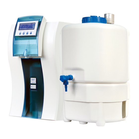
Particles****(0.22μm) /ml <1 Dispensing rate L/H 60-100 Power Consumption W Weight kg Storage tank Main System Dime. W*D*H 525*314*571 Storage Tank Dime.W*D*H 430*380*580 2.4 Diagram of the Smart-NE system... -
Page 9: Chapter 3 Instructions Before Installation
Chapter 3 Instructions before installation 3.1 Check before installation Users please ensure whether the product you received is your purchase before installation. You had batter check all items according the packing list. Whether the power site is close to the system. ... -
Page 10: Chapter 4 Installation
Chapter 4 Installation It is important for the user to master installation and removal of quick connector. If user dose not operate properly will lead to water leakage, quick connector damage and pipeline broken. 4.1 Accessory installation of storage tank First to twine the 1/2’... -
Page 11: Pipeline Connections Between Main Unit And Rwd
Floor drain Cut a white tube, insert one end of the tube into the "OUT" on the back of main unit, and the other end into the "IN" on the back of storage tank. Cut a white tube, insert one end of the tube into the "IN" on the back of main unit, and the other end into the "OUT"... -
Page 12: Level Cable
Water tank Main unit Remote water dispenser Foot control 4.3.1 Level cable Connect the seven core signal cable on the top of the water storage tank to the level sensor socket on the back of the main unit. 4.3.2 Pump power cable Get the three core signal cable, one end connect to three core socket at the back of main unit, the other end connect to the three core socket at the back of storage tank base. -
Page 13: Installation Of Pretreatment Cartridge
A Pretreatment cartridge B RO cartridge C UV light D EDI E Ultrapure cartridge F MF/UF cartridge 4.4.3 Installation of pretreatment cartridge Confirm the system is power off. Pretreatment cartridge is installed in the right chamber of Smart-NE system. Get the pretreatment cartridge from the box (make sure number is correct for the CR-SP101M), open the vacuum bag, remove protection cover for the inlet and outlet of pretreatment cartridge. - Page 14 Press and pull the latch at the top of the front door, to remove the front door (press down about 3mm, do not press down hardly which may cause deformation or even fracture bayonet). Open the front door of the system. Please refer to this chapter. Open the front door, the cabinet of ultra-purification cartridges has upper and lower latch.
-
Page 15: Chapter 5 Parameter Setting And Operation
Chapter 5 Parameter setting and operation 5.1 Control panel area Smart - NE 25.0°C Ultra-water Dispensing UP: 18.2 MΩ · cm Vol Disp: OFF 08:00 20/09/2016 St op St op DI SP. DI SP. Fl ush Fl ush M enu M enu A: dashed box for the LCD display area. -
Page 16: Operation
5.5 Operation Turn on feed water supply. Ensure that all the pipe connecting parts have no leaking. Switch on the power supply at the back of the main unit. After the main unit is powered on, LCD will display a welcome message, which is followed by the current state of the system. -
Page 17: Parameters Setting
Smart - NE 25.0°C Standby Cycling... Cycling... 08:00 20/09/2016 5.6 Parameters setting Press "Menu" keypad to enter the menu 语言 LANGUAGE 中文 ENGLISH Press "Disp./▲" or "Flush/▼" keypad to select "ENGLISH". Press the "Stop /" keypad to confirm the setting and to the next level. Password: 85 Press or hold down the "Disp. - Page 18 UV UV 4000h 4000h 6000h 6000h 8000h 8000h life life : PF PF life life UF UF life life RO RO DS DS UV UV life life Feed Feed In this menu level the maintenance interval for the UV oxidator of main system must be reset after exchanging the UV lamp.
-
Page 19: Calendar Setting
system shows the alarm message “Ds light” if the adjusted limit will be overstepped (manufacture’s setting is 90%). press “Disp./▲,Flush/▼”keypad to increases or decreases the value, press the Stop/” keypad to confirm the setting and switches to the next menu level. This value should not be set too low, otherwise the pure water quality will be affected. -
Page 20: Ultra-Pure Water Quality Setting
Dispensing Dispensing 1.50 1.50 flow flow Alarm Alarm Prod. Prod. Calender Calender setting setting unit unit Disp. Disp. Volume Volume Prod. Prod. of of water water Resis. Resis. flow flow Note: Suggestion the user had batter to calibrating fixed quantity every half month. 5.6.5 Ultra-pure water quality setting After entering the parameter setting menu according to this chapter, press “Disp./▲”or “Flush/▼”keypad to select the "Prod. -
Page 21: Chapter 6 Maintenance
Chapter 6 Maintenance 6.1 Routine maintenance Maintenance of the ultra-pure water system is simple and convenient despite its integration of sophisticated equipment which combines water process, computer-control and precision instruments to monitor. Keep feed water going smoothly. Please stop main unit when feed water is cut off so that you can avoid large numbers of impurities in the water flowing into the apparatus, it will decrease the life time of pre-treatment cartridge. -
Page 22: Into The Maintenance Settings
Take the filter core out and washed with flowing pure water or brush. Pay attention to the seal o-ring which should be attached to the filter. After cleaning, put the filter core to the original place and tighten the lid. Ensure that the core and seal o-ring in the lid. -
Page 23: Membrane Replacement
After entering maintenance settings, press “Disp./▲” or “Flush/▼” button to choose “Cartridge replace”, then press “Stop/” keypad to confirm to enter each setting in replacement of supplies. Replace Replace PF? PF PF UF UF DI DI UV UV RO RO Press “Disp./▲”or “Flush/▼”... - Page 24 Replace Replace RO? PF PF UF UF DI DI UV UV RO RO Press “Stop/”keypad to confirm, LCD will display the confirmation interface of consumable replacement. RO RO Replaced? Replaced? PF PF UF UF DI DI UV UV RO RO Remove the left side door of the main unit (front view).
-
Page 25: Purification Cartridge Replacement
conductivity of pure water high. After the replacement is done, press the "Flush / ▼" button of the control panel to flush the reverse osmosis membrane. Repeat 10 to 15 times of flush. 6.3.5 Purification cartridge replacement Please refer to this chapter to enter the maintenance setting interface, press the "Disp. / ▲" or "Flush / ▼"... -
Page 26: Micro/Ultra-Filter Replacement
Remove the right side door of the main unit (front view). UV lamps are installed in the right chamber of the Smart-NE system, mounted on the UV lamp holder. Unplug the power cord of the UV lamp. Remove the exhausted UV lamp. Please refer to the following diagram (cutaway view of the back of the chamber). -
Page 27: Re-Install The Cartridges
Press "Stop / " keypad to confirm, LCD displays the replacement complete. UF UF Replaced? Replaced? PF PF UF UF DI DI UV UV RO RO Remove the right side door of the main unit (front view). Micro-filter installed in the right chamber of the Smart-NE system. The MF/UF is bolted to the rack of the main unit. -
Page 28: Obligate Level Setting
FEED: the current feed water conductivity. RO: pure water conductivity. DS: Desalination rate for reverse osmosis cartridge. T: the current system temperature. PF: used time for pretreatment cartridge. UV: used time for ultraviolet lamps. MF: used time for Micro-filter cartridge. UP: resistivity of ultra pure water Press "Menu"... -
Page 29: Restore Factory Settings
<00001> <00001> 11:00 11:00 20/09/2016 20/09/2016 25.2℃ 25.2℃ 390μS/cm 390μS/cm 15.0μS/cm 15.0μS/cm 18.2MΩ.cm 18.2MΩ.cm 12.4L 12.4L 00012.4L 00012.4L <00002> <00002> 12:00 12:00 21/09/2016 21/09/2016 25.0℃ 25.0℃ 400μS/cm 400μS/cm 15.2μS/cm 15.2μS/cm 18.2MΩ.cm 18.2MΩ.cm 15.6L 15.6L 00028.0L 00028.0L The first line from left to right: product water dispenses times, time and date. Second line from left to right: water temperature, feed water conductivity and pure water conductivity. -
Page 30: Main Unit Disinfection
Press "Menu" keypad to return to the previous menu, or press "Menu" keypad continuously to exit the maintenance setting, the system reboots. When the restart of system is complete, each parameter value is automatically set back to manufactory setting. Manufactory settings for all parameters are as follows: Pretreatment cartridge alarm time: 400h UV lamp alarm time: 4000h Micro-filter cartridge alarm time: 6000h... - Page 31 Disinfection Disinfection End Press "Stop / " keypad to confirm, the system restart. After the system restarts, press the "Disp. / ▲" keypad to flush the remaining disinfectant in the end tube for 10-15 minutes.
-
Page 32: Chapter 7 Troubleshooting
Chapter 7 Troubleshooting 7.1 No display Description Solution No power supply for power outlet Confirm power outlet is normal Electrical outlet loose Change electrical outlet System power cord is not properly installed Make sure the power cord is plugged into the electrical outlet of main unit system power is turned off Turn on the power switch on the back of the... -
Page 33: Chapter 8 Order Information
Chapter 8 Order information 8.1 Consumable Description specification Order No. Pre-filter 2’tube connector CR-SP109 Pretreatment cartridge 10um/5um PP and active carbon CR-SP101M RO membrane 100G CR-SP202 Purification cartridge CR-SP302M Purification cartridge CR-SP303M) Air filter CR-SP412 Micro-filter CR-SP502B Ultra-filter CR-SP505 UV sterilizer lamp 254/185nm CR-SP431 Final filter... -
Page 34: Chapter 9 Appendix
Chapter 9 Appendix Appendix 1 Fuse replacement The fuse used by the system is 1A/250V, which is installed in the power outlet at the back of the main unit. Pull the power cord from the external power outlet. Unplug the power cord from the main unit. You can see a fuse holder below the power socket. Use a screwdriver to pull the fuse holder from socket. -
Page 35: Appendix 3 Inlet Valve Unit Installation
Appendix 3 Inlet valve unit installation Some of the laboratories have no threaded tap. The fast connection can not be used to connect to an external water supply pipe. The inlet valve components can be optional alternative, which is installed in the middle of external pipe. - Page 36 Pl u g Pl u g CEL L CEL L CEL L CEL L RT RT RT RT CEL L CEL L CEL L CEL L CEL L CEL L CEL L CEL L RT RT RT RT P1 P1 P3 P3 P2 P2 Ce l l...
- Page 37 Global Exclusive Agent Nison Instrument (Shanghai) Limited Address: Floor 16th, 1065 West zhongsan Road, Shanghai, P.R.China TEL: 86-21-62728646, 62712931 FAX: 86-21-62710529 E-mail: export@hf.healoo.com Website: www.healforce.com Manufacturer Shanghai Canrex Analytic Instrument Co, Ltd. Address: No.4 Workshop Building, 298 Lian-Zhen Rd. Pudong Shanghai P.R.China...
Need help?
Do you have a question about the Smart-NE Series and is the answer not in the manual?
Questions and answers