Table of Contents
Advertisement
Quick Links
Advertisement
Table of Contents

Related Manuals for Heal Force Smart-Mini

Summary of Contents for Heal Force Smart-Mini
- Page 1 Smart-Mini Water Purification System Operation and Service Manual Version:1501...
- Page 2 Preface Thank you for using Smart-Mini water purification system designed and manufactured by Shanghai Canrex Analytic Instrument Co, Ltd. If you have any good suggestion, Please contact us, we will improve our products and after sale service continuously.
- Page 3 ISO 9001:2008 Certificate...
-
Page 4: Table Of Contents
Chapter 2 System Introduction....................3 2.1 System principle......................3 2.2 Technical features......................3 2.3 Specifications for the system..................4 2.4 Diagram of the Smart-Mini system................5 Chapter 3 Instructions before installation................7 3.1 check before installation....................7 3.2 Option spare parts......................7 3.2.1 Systematic data recording package CR-SP840............7 3.2.2 Enhanced pretreatment cartridge CR-SP102............ - Page 5 6.3.3 RO membrane replacement................29 6.3.5 UV lamp replacement..................33 6.3.6 Micro-filter replacement..................34 6.3.7How to re-installation when the cartridges are not installed in the right place...36 6.4 System status check..................... 36 6.5 Data record of system....................37 6.7 Restore factory settings....................39 Chapter 7 Troubleshooting.....................40 7.1 No display........................
-
Page 6: Chapter 1 General
Safety information You must use the safety norms according to this manual before using the Smart-Mini system, especially water and power supply. It is necessary to refer to this manual when you install or operate the Smart-Mini system. Unqualified using environment will endanger the normal operation, or even damage the whole system. -
Page 7: Warnings Signal
No heat source next to the equipment. Be away from strong magnetic field. 1.4 warnings signal Note alert you to pertinent facts and conditions, please read this operation and service manual carefully before you operate the main system Caution: Caution alert you to the possibility of damage to the equipment, and water in pipe may spill out when the cartridge is installed OR replaced. -
Page 8: Chapter 2 System Introduction
CPU auto-control technology, highly integrated water treatment equipment. It is the new generation of intelligent water purification system with intellectual property. The feed water of Smart-Mini system is ordinary tap water. The feed water is passing through the multi-channel process of pretreatment cartridge, reverse osmosis cartridge, purification cartridge, Ultra-purification cartridge ,UV sterilizer, Micro-filter cartridge. -
Page 9: Specifications For The System
RS232 port allows for data collection and permanent record of water quality and system parameters--essential for compliance with good laboratory practice guidelines. With remote monitor software (option),you can remote the water system on the computer. 2.3 Specifications for the system Smart-Mini Conductivity μS/cm@25℃ <400 Feed water Pressure MPa 0.1~0.4... -
Page 10: Diagram Of The Smart-Mini System
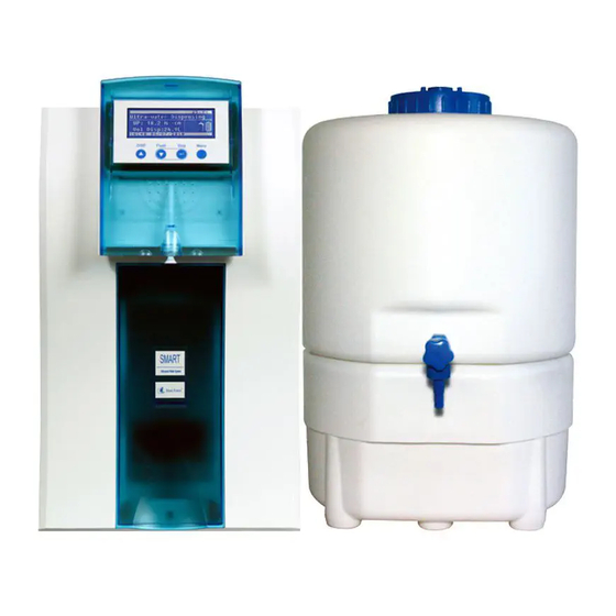
2.4 Diagram of the Smart-Mini system Smart-Mini... - Page 11 Diagram of controller and measurement CELL CELL low pressure sensor black blue cell 1 plug CELL CELL BREAK IN blue green yell cell 2 black green CELL CELL GND ACD ACA ACB ACE ACF yel blu yel whi whi bro bro fuse temp cell 3...
-
Page 12: Chapter 3 Instructions Before Installation
3.2.1 Systematic data recording package CR-SP840 It includes systematic data recording software and RS232 connecting signal. Using it, you can easily have SMART-MINI system and your computer connected, on which you can install and record you using this recording system and water quality. - Page 13 Enhanced pretreatment cartridge is a multi-stage pretreatment module to removes the impurities in tap water including suspended particulates, colloids, microorganisms, organics, chlorine and heavy metals to ensure the following purification modules work properly.
-
Page 14: Chapter 4 Installation
Chapter 4 Installation It is important for the user to master installation and removal of quick connector. If user dose not operate properly will lead to water leakage, quick connector damage and pipeline broken, 4.1 Pipeline connections feed water pre-filter drain drain drain... -
Page 15: Signal Cable Connection
4 .2 Signal cable connection 1, socket for leakage sensor 2, Power on/off 3, socket for power supply 4,socket for USB(option) . 4.3 Pretreatment installation 4.3.1 open the side door of the main unit Opening method is showed below Step A: unscrew the screw of the side door with a screwdriver. Step B: pull the handle of the side door with both hands, forced back to pull the a side door out of 10mm ~ 13mm. -
Page 16: Installation Of Pretreatment Cartridge
4.3.3 Installation of pretreatment cartridge Confirm the Smart-Mini system is power off. Pretreatment cartridge is installed in the right chamber of smart-Mini system. Get the pretreatment cartridge from the box (make sure number is correct for the CR-SP101M), open the vacuum bag, remove protection cover for the inlet and outlet of pretreatment cartridge. -
Page 17: Installation Of Ultra-Purification Cartridge (Cr-Sp302M)
4.3.4 Installation of ultra-purification cartridge (CR-SP302M) Remove the left side door (front view), please refer to of this chapter. Ultra-Purification cartridge is installed in the left chamber of Smart-Mini system. Get the ultra-purification cartridge from the box (make sure number is correct for the CR-SP302M). - Page 18 As shown in figure “A””B” Installation of purification cartridge(CR-SP301MS) Open the front door of the Smart-Mini system. Please refer to this chapter. Open the front door , the cabinet of ultra-purification cartridges has upper and lower latch, As shown in Figure A Take out the ultra-purification cartridge from the box (make sure number is correct for the CR-SP303M), open the vacuum bag, remove protection cover for the port of cartridge.
-
Page 19: Chapter 5 Parameter Setting And Operation
Chapter 5 Parameter setting and operation 5.1 Control panel area A: dashed box for the LCD display area. B: dashed box for the function keypad board. 5.2 LCD display area A: system model and the current temperature display . B: current status C: product water quality and Volume dispense status. -
Page 20: Function Keypad
5.4 Function Keypad There are 4 function keypads in Smart-Mini system: disp./ ▲ , Flush/ ▼ , Stop/ and Menu Disp./ ▲ Dispense product water keypad at the operation, it will be become adjusting keypad at the menu mode. - Page 21 . But the Smart-Mini system will enter the standby mode. As shown below: rate Smart-Mini has manual flush function for RO membrane cartridge, press the "Flush / ▼ " to flush RO membrane cartridge manually for 1 minute. At this time the LCD display of the main unit is the same as flushing mode from the beginning.
-
Page 22: Parameters Setting
Press "Disp. / ▲" keypad you can take the pure water. If the quality of current ultrapure water can not meet the requirement of original setting (ie 16.0MΩ.cm), the system will automatically enter recycling mode to improve the water quality. And if the water quality reaches the set value, the main unit starts to produce ultra-pure water. -
Page 23: Alarm Settings
Press "Disp / ▲ " or "Flush / ▼ " keypad to select "ENGLISH" .White on Black means that has been selected, press the "Stop / " keypad to confirm the setting and to the next level. As shown below: Press or hold down the "Disp. - Page 24 After entering the parameter setting menu, press the "Disp. / ▲ " or "Flush / ▼ " keypad to select "Alarm setting" White on Black means it has been selected. Press the "Stop / " keypad to confirm the settings menu to enter the alarm category including various settings, as shown below: 400h 500h...
- Page 25 life : 4000h 6000h 8000h PF life MF life UV life Feed In this menu level the maintenance interval for the Micro-filter Cartridge life time of main system must be reset after exchanging the cartridge. the manufacture setting is 4000hour for Micro-filter Cartridge life time, the user can press “Disp./▲, Flush/▼” keypad to select one of the 4000,5000,6000 hour according to the user de sire.
-
Page 26: Calendar Setting
will be overstepped it will decrease the life time of purification cartridge. the manufacture setting is 20us/cm, the user can press “Disp./▲,Flush/▼” keypad to adjusting according to the user desire. Press the “Stop/ ” keypad to confirms the setting and switches to the next menu level If this value is set too large, then the performance and lifetime of the ultrapure water purification cartridge will be affected. -
Page 27: Volume Of Taking Product Water Setting
level. Y e a r 2 0 1 5 Y e a r M o n t h D a t e 2 0 1 5 H o u r M in u t e 5.6.3 Volume of taking product water setting After entering the parameter setting menu , press “Disp./▲”或“Flush/▼”keypad to select the "Volume of water"... -
Page 28: Ultra-Pure Water Quality Setting
Note: Suggestion the user had batter to calibrating fixed quantity every half month. 5.6.5 Ultra-pure water quality setting After entering the parameter setting menu according to this chapter, press “Disp./▲”or “Flush/▼”keypad to select the "Prod. Resis." function. White on black means it has been selected. - Page 29 Prod. μs/cm MΩ · Unit Alarm Calendar Prod. setting Unit Volume Prod. of water Resis. In this menu level the user can select the display unit of product water , the user can press “Disp./▲,Flush/▼” keypad to selecting one of “MΩ.cm” “or us/cm” according to the user desire.
-
Page 30: Chapter 6 Maintenance
Keep both indoor environment and the instrument surface clean. If you need to stop main unit for a period, please keep in mind that firstly you should press “flush” keypad to flush the Smart-Mini system , then have the inlet valve closed and power off. -
Page 31: Maintenance Works And Service Works
decrease/ a mention of Ultra-Purificatio replace n cartridge Ultra-pure water index decreased or a mention of replace Product water dispense decrease,or a mention of replace A mention of Final filter Replace at same time with ultra-purification cartridge replace 6.3 Maintenance works and service works Be sure to enter the service setting by press”... - Page 32 Make sure that the system is in standby or automatic making water state. If it is in flushing or dispense state, please press “Stop/”to stop it. Press “Menu” keypad to enter the menu model, first of which is the language option. As is shown below: 语言...
-
Page 33: Pre-Treatment Replacement
As is shown below: PF replcaed? Remove the pre-treatment from the Smart-Mini. As is shown below: exhausted cartridge We have completely removed the main unit shell so that it is easy for you to see clearly. -
Page 34: Membrane Replacement
In fact, during the installment you just need to remove the main unit side door and after that you can finish the replacement Remove the right side door ( front view ) of the main unit. As for the operation procedure, Pre-treatment cartridge is installed right in front of the host cavity and mounted on the connector of the water. - Page 35 consumable replacement. RO replaced? Remove the left side door of the main unit (front view). RO cartridge is installed at the back of the left chamber, which the ordering No is CR-SP201 or202. Remove the connecting pipe from the RO cartridge. The upper single pipe is inlet pipe; the middle pipe at the bottom is for pure water, while the side one in lower position is for waste water discharge.
- Page 36 Insert the tube into the corresponding connectors of the RO cartridge. Install the RO module back on the rack of chamber. Install the side door of the main unit. Back to the control panel operation, press the "Stop / " keypad to confirm the replacement.
- Page 37 Install the purification cartridge into the main unit, Install the side door. Ultra-purification cartridge replacement(CR-SP303M) Open the front door of the Smart-Mini system. Please refer to 4.3.5of chapter 4. Open the front door, then you can see upper and lower latches inside the main unit. Take out of the latches.
-
Page 38: Uv Lamp Replacement
Remove the right side door of the main unit (front view). Please refer to the section 3,1 of this chapter. UV lamps are installed in the right chamber of the Smart-Mini system, mounted on the UV lamp holder. Unplug the power cord of the UV lamp. -
Page 39: Micro-Filter Replacement
Pull out the inlet/outlet water tube of the UV lamp, mark the connector to avoid mistakes in the next installation process. Unscrew the fixer of the UV lamp, as shown in figure A. Remove the UV lamp hoop, as shown in B. Remove the UV light from UV lamp holder out. - Page 40 MF replaced? Remove the right side door of the main unit (front view). Micro-filter installed in the right chamber of the Smart-Mini system. The MF is bolted to the rack of the main unit. Remove the connection pipe from the Micro-filter, You can mark the tube to prevent confusion in the next installation.
-
Page 41: 7How To Re-Installation When The Cartridges Are Not Installed In The Right Place
6.3.7How to re-installation when the cartridges are not installed in the right place. The system will leak water when the cartridge installation has some mistakes. The cartridges re-installation is needed. Refer to the following content. Refer to this chapter and enter the maintenance setting, press the "Disp. / ▲" or "Flush / ▼... -
Page 42: Data Record Of System
6.5 Data record of system Smart-Mini system is equipped with a large capacity data storage units, it will record time, temperature, quality, each water producing volume, the total water producing volume, the time, the type and the replacement frequency of cartridges. - Page 43 <00001> 11:00 01/02/2015 25.2℃ 390μ S/cm 15.0μ S/cm 18.2MΩ .cm 12.4L 00012.4L <00002> 12:00 02/02/2015 25.0℃ 400μ S/cm 15.2μ S/cm 18.2MΩ .cm 15.6L 00028.0L Data Description: The first line from left to right: product water dispenses times, time and date. Second line from left to right: water temperature, feed water conductivity and pure water conductivity.
-
Page 44: Restore Factory Settings
replacement records. Press "Menu" keypad to return to the previous menu, or press "Menu" keypad continuously to exit the maintenance setting, the system restart. 6.7 Restore factory settings Various parameter settings has been changed by users. When you need to return to the default settings, you can choose this item. -
Page 45: Chapter 7 Troubleshooting
Chapter 7 Troubleshooting 7.1 No display Description Solution No power supply for power outlet Confirm power outlet is normal Electrical outlet loose Change electrical outlet System power cord is not properly installed Make sure the power cord is plugged into the electrical outlet of main unit system power is turned off Turn on the power switch on the back of the... -
Page 46: The Pure Water Conductivity Is Too High
7.3 The pure water conductivity is too high Description solution Feed water conductivity is high Choose RO-2 module RO exhausted, showing RO or DS alarm Replace the RO membrane reverse osmosis membrane with Press “ Flush/ ▼ ” button to rinse the remaining protection liquid. -
Page 47: Chapter 8 Order Information
Order No. Remark Leakage protection sensor Round water detect CR-SP846 sensor Enhanced pretreatment Pretreatment CR-SP102 device cartridges Pretreatment filter 2sets 20”PP,AC,SR CR-SP107 Pressure limiter CR-SP829 Inlet valve subassembly 4” T-way with 2 CR-SP831 “ball valve Data transfer software Smart-Mini CR-SP840... -
Page 48: Chapter 9 Appendix
Chapter 9 Appendix Appendix 1 Fuse replacement The fuse used by the system is 1A/250V, which is installed in the power outlet at the back of the main unit. Pull the power cord from the external power outlet. Unplug the power cord from the main unit. You can see a fuse holder below the power socket. -
Page 49: Appendix 2 Pressure Limiter Installation
Appendix 2 pressure limiter installation The feed water pressure for the system is normally 0.4MPA. If the pressure exceeds this value, a pressure limiter needs to be installed after the pre-filter, as shown below. to main system pressure limiter Please install the pressure limiter according to the water flow direction, do not install it in the wrong direction, otherwise it will not work normally. -
Page 50: Appendix 3 Inlet Valve Unit Installation
Appendix 3 inlet valve unit installation Some of the laboratories have no threaded tap. The fast connection can not be used to connect to an external water supply pipe. The inlet valve components can be optional alternative, which is installed in the middle of external pipe. Inlet valve subassembly is usually installed on the outside of the tap, as shown below. -
Page 51: Appendix 4 Leakage Protection Sensor Installation
Appendix 4 Leakage protection sensor installation Get the cable one end connect to hole at the back of main unit, the other end to the Leakage protection sensor, Put the leakage protection sensor on the table near the main unit. -
Page 52: Appendix 5 Components Connection To Main-Board
Appendix 5 Components connection to main-board The joints P11, P12 P13 and P14 of the mainboard have 220V or 110V voltage. User should not arbitrarily open the main unit shelter. ACC GND ACD ACA ACB ACE ACF 220V(IN) EGND CELL CELL CELL CELL... - Page 53 Global Exclusive Agent Nison Instrument (Shanghai) Limited Address: Floor 16th, 1065 West zhongsan Road, Shanghai, P. R. China TEL: 86-21-62728646, 62712931 FAX: 86-21-62710529 E-mail: export@hf.healoo.com Website: www.healforce.com Manufacturer Shanghai Canrex Analytic Instrument Co, Ltd. Address: No.4 Workshop Building, 298 Lian-Zhen Rd. Pudong Shanghai 201204, P.
Need help?
Do you have a question about the Smart-Mini and is the answer not in the manual?
Questions and answers