
Related Manuals for Bathology Atmospheric 310


Summary of Contents for Bathology Atmospheric 310
- Page 1 B A T H O L O G Y r e d i s c o v e r b a t h i n g A t m o s p h e r i c 310 I n - S h o w e r V e n t i l a t i o n I n s t a l l a t i o n a n d O p e r a t i o n M a n u a l...
- Page 2 A t m o s p h e r i c 310 B A T H O L O G Y Components Spec Install Page Page Vibration Isolation Grommet 100 CFM 6 - 8 Exhaust Fan, 4” 1” Screws Mounting Bracket 7/16”...
-
Page 3: Vent Options
A t m o s p h e r i c 310 B A T H O L O G Y Components Continued Spec Install Page Page Expansion Vent Options No Light Expansion Vent 9 - 12 Hanger Bars Housing, 4” duct Expansion Vent 1”... - Page 4 A t m o s p h e r i c 310 B A T H O L O G Y Typical Installation - Exterior Roof Important: It is recommended that all electrical equipment be tested prior to installation. Page ID Product 6 - 8 Exterior Roof...
- Page 5 A t m o s p h e r i c 310 B A T H O L O G Y Typical Installation - Wall Exhaust Important: It is recommended that all electrical equipment be tested prior to installation. Page ID Product Exterior Wall 6 - 8...
-
Page 6: Installation
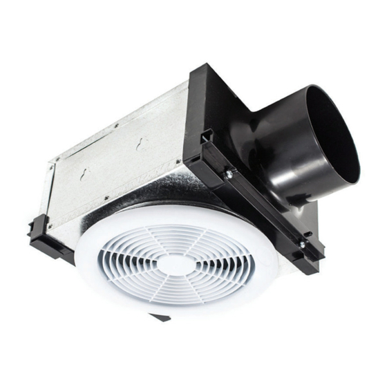
A t m o s p h e r i c 310 B A T H O L O G Y Fan Specifications and Installation Specifications Installation Stud / Ceiling Joist 100 CFM Fan Operating Voltage: 120VAC 1” Screw Power Consumption: 21.1W Nominal Amperage: 0.18 Amps CFM: 100 @ .20”... - Page 7 A t m o s p h e r i c 310 B A T H O L O G Y Fan Installation Installation Considerations Warning: For your safety, read and understand Warning: Check voltage at the fan to see if it instructions completely before starting.
-
Page 8: Fan Installation
A t m o s p h e r i c 310 B A T H O L O G Y Fan Installation Using the 1” wood screws (4) provided, attach Secure the romex connector. Secure the the fan mounting bracket (2) to a support beam incoming supply with the romex connector. -
Page 9: Installation Considerations
A t m o s p h e r i c 310 B A T H O L O G Y Housing Specifications and Installation Installation Considerations Specifications Warning: For your safety, read and understand Expansion Vent Options instructions completely before starting. Before wiring to No Light power supply, turn off electricity at the fuse or circuit breaker box. - Page 10 A t m o s p h e r i c 310 B A T H O L O G Y Expansion Ventilation Specifications and Installation Expansion Vent Housing Installation Mounting Directly to Joist Mounting Brackets to Joist Expansion Vent Expansion Vent Housing Housing...
- Page 11 A t m o s p h e r i c 310 B A T H O L O G Y Expansion Ventilation Installation Important: It is recommended that all electrical equipment be tested prior to installation. Installation Based on the bathroom layout and fixtures, Cut a 6"...
- Page 12 A t m o s p h e r i c 310 B A T H O L O G Y Expansion Ventilation Installation 7. Install the bulb by gently inserting it into the Halogen Bulb Install socket in the expansion vent housing (1). Install the expansion vent grille (2) by pushing it firmly into the steel collar until it is shouldered by the Expansion Vent...
- Page 13 A t m o s p h e r i c 310 B A T H O L O G Y Control Specifications and Installation Specifications Installation Considerations Warning: For your safety, read and understand Electronic Time Control instructions completely before starting. Before wiring to power supply, turn off electricity at the fuse or circuit Operating Voltage: 120VAC, 60Hz breaker box.
-
Page 14: Control Installation
A t m o s p h e r i c 310 B A T H O L O G Y Control Installation Timer / Fan Wiring Hot (Black) Black White Green Line 120VAC Ground Black 60Hz Neutral (White) White Timer / Light / Fan Wiring Black Hot (Black) -
Page 15: Operation
A t m o s p h e r i c 310 B A T H O L O G Y Control Installation Important: It is recommended that all electrical equipment be tested prior to installation. Installation To change faceplate of electronic time control (1), push in the side of the faceplate at the tabs to release. - Page 16 A t m o s p h e r i c 310 B A T H O L O G Y Damper Specifications / Installation Specifications Installation Damper Expansion Vent Damper Dimensions: 4” Diameter x 6” Length Screw Damper Input to Label must Body Composition: 28 guage galvanized steel Expansion Vent Housing...
- Page 17 A t m o s p h e r i c 310 B A T H O L O G Y Roof Cap / Wall Vent Specifications and Installation Specifications Installation Roof Cap, 4 Roof Cap Composition: Galvanized Steel Rough-in Cutout: 4-1/8” Duct Connection: 4”...
- Page 18 A t m o s p h e r i c 310 B A T H O L O G Y Duct Specifications and Installation Specifications Installation Exhaust to Roof Flex Duct, 4” Cap or Wall Vent Dimensions: 4” Diameter x 25’ Length Insulation: Fiberglass Flex Duct 100 CFM Fan...
- Page 19 B A T H O L O G Y r e d i s c o v e r b a t h i n g Note: Wash with soap and warm water after www.Bathology.com 847-465-1070 handling. A division of Bathing Brands, Inc.
Need help?
Do you have a question about the Atmospheric 310 and is the answer not in the manual?
Questions and answers