Table of Contents
Advertisement
Quick Links
Advertisement
Table of Contents

Subscribe to Our Youtube Channel
Related Manuals for PairGain HiGain Wideband System 3190


Summary of Contents for PairGain HiGain Wideband System 3190
- Page 1 HiGain Wideband System 3190 Installation Guide Model List Number Part Number CLEI Code HMS-357 150-2205-01 T3M1FH0ERA HMS-357 150-2205-02 T3M1GH0ERA AIR AIN ECHNOLOGIES, NC. NGINEERING ERVICES ECHNICAL RACTICE ™800-357-100-01v¨ 800-357-100-01 ECTION...
- Page 2 Information furnished by PairGain Technologies is believed to be accurate and reliable. However, no responsibility is assumed by PairGain Technologies for its use; nor for any infringement of patents or other rights of third parties which may result from its use.
- Page 3 Cautions indicate the possibility of equipment damage or the possibility of personal injury. BOUT ANUAL This manual provides an overview of the HiGain Wideband System 3190, its features, applications, and main system components. Step-by-step installation instructions begin on page 13 and lead you through basic system setup and provisioning.
- Page 4 Related Documentation 800-357-100-01, Revision 01 February 2, 1999 HMS-357 List 1...
-
Page 5: Table Of Contents
800-357-100-01, Revision 01 Table of Contents ABLE OF ONTENTS Product Overview_____________________________________________________________________ 1 Features ..............................2 Application............................2 Product Description..........................3 Chassis ..........................4 Multiplexer Unit ........................5 System Management Unit ....................6 HiGain Line Units .......................7 HiGain Test and Loop-through Card...................8 HiGain Remote Units ......................9 HiGain Doubler Units......................9 Fan Assembly ........................10 Interfaces ...........................11 Alarms ..........................12... - Page 6 Table of Contents 800-357-100-01, Revision 01 Installing the Multiplexer Cards...................... 31 Setting up the Communications Channel to the HXU-357..........32 Setting up System Administration ..................32 Configuring the HXU DS3 Interface ................33 Placing the HXU DS3 Interface In Service ..............33 Configuring the HXU DS1 Interface....................
- Page 7 800-357-100-01, Revision 01 Table of Contents Managing Alarms..........................69 HMU Alarms ........................69 HXU Alarms........................69 When an Alarm Occurs .....................70 Shelf Alarms for Multishelf Configurations..............70 Line Unit Alarms .......................71 Changing the Logon Password ......................71 Logging Off............................73 Troubleshooting _____________________________________________________________________ 74 Installing a HiGain Test Card ......................75 Appendix A - System Specifications _____________________________________________________ 76 Interface Specifications........................76 HXU-357 Multiplexer Card Specifications ..................80...
- Page 8 Table of Contents 800-357-100-01, Revision 01 Network Addresses.......................... 94 Hardware Addresses and IP Addresses................94 Subnet Mask........................94 Routers or Gateways ......................95 Trap IP Address ........................ 95 Appendix C - Service and Support ______________________________________________________ 96 Technical Support..........................96 BBS ........................... 96 World Wide Web ......................
- Page 9 800-357-100-01, Revision 01 List of Figures IST OF IGURES HiGain Wideband System 3190 ........................1 HiGain Wideband System 3190 Application ....................2 Front View of 3190 Chassis (Cover Removed) ..................4 HXU-357 Multiplexers ..........................5 HMU-319 List 7 and List 7A ........................6 Typical HLU-319 Line Unit........................7 HTC-319 List 1 Test and Loop-through Card...................8...
- Page 10 List of Figures 800-357-100-01, Revision 01 Power Connector (TB1).......................... 76 Alarm Relays (TB2) ..........................76 HDSL Loop Cable and Connector......................79 Location of Bar Code Label and Configuration Number ............... 98 February 2, 1999 HMS-357 List 1 and List 2...
- Page 11 800-357-100-01, Revision 01 List of Tables IST OF ABLES Main Chassis Components ........................4 HXU-357 Multiplexer Indicators ......................5 CSA Range..............................9 Wideband System 3190 Interfaces ......................11 Installation Tools.............................15 Summary of Installation Tasks........................17 Shelf Options Menu Parameters ......................56 Keyboard Commands..........................61 Configuration Management ........................63 Performance Management ........................65 Fault Management...........................65 System Configuration Status........................66...
- Page 12 List of Tables 800-357-100-01, Revision 01 February 2, 1999 HMS-357 List 1 and List 2...
-
Page 13: Product Overview
This open architecture allows any industry-compliant 3192 card to function in a managed DS3-based shelf. PairGain recommends that third-party line units be certified for compliance in a Wideband System 3190 shelf. -
Page 14: Features
Compatibility with industry-standard DS3 trunk circuits • Compatibility with industry-standard 3192 channel cards • Integrated open-management system based on PairGain’s single-wire management of HLU cards • Compatibility with existing HiGain line units, doublers, and remote units • NEBS and UL compliance at a system level •... -
Page 15: Product Description
For more complete information about the HXU-357, the HFA-357, the HMU-319, and the various HDSL units, refer to the appropriate practices for those products. See “Appendix C - Service and Support” on page 96 for information on how to contact PairGain Technologies, Inc. HMS-357 List 1 and List 2 February 2, 1999... -
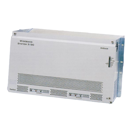
Page 16: Chassis
Product Overview 800-357-100-01, Revision 01 Chassis • Product Name: HMS-357 List 1 and List 2 • Part Number: 150-2205-01, 150-2205-02 Heat baffle / fiber tray 3190 shelf Heat baffle / ESD strap input fan tray Dual M13 tray in. (30.8 cm) (54.3 cm) 12 in. -
Page 17: Multiplexer Unit
800-357-100-01, Revision 01 Product Overview Multiplexer Unit • Product Name: HXU-357 List 1 • Part Number: 150-2206-01 Figure 4. HXU-357 Multiplexers There are two multiplexer cards mounted in the multiplexer tray. One is the active card and the other serves as a backup if the active card fails. -
Page 18: System Management Unit
RS-232 Craft port Barcode label Figure 5. HMU-319 List 7 and List 7A The Wideband System 3190 is managed by PairGain’s standard HMU-319 management card. The HMU-319 provides network management and communication capabilities for HDSL T1 transmission service over unconditioned copper wires. -
Page 19: Higain Line Units
DSX-1 access jacks Craft port PairGain Figure 6. Typical HLU-319 Line Unit The HiGain HLUs provide a repeaterless, T1 transmission system to and from the CO. When installed in a System 3190 and used with a HiGain Remote Unit (HRU), each line unit delivers 1.544 Mbps transmission on two unconditioned copper pairs over the full Carrier Service Area (CSA) range. -
Page 20: Higain Test And Loop-Through Card
Figure 7. HTC-319 List 1 Test and Loop-through Card The PairGain HTC-319 is an optional test card that plugs into any 3192 shelf slot. It provides access to test points on CO, DSX-1, and field circuits. When used with the HXU-357 List 1, it features: •... -
Page 21: Higain Remote Units
3, each additional doubler increases the range by the original CSA length (12,000 feet [3.7 km] of 24 AWG or 9,000 feet [2.7 km] of 26 AWG). PairGain manufactures a complete line of doubler units to address all standard industry enclosures. (see “HiGain System Products”... -
Page 22: Fan Assembly
Product Overview 800-357-100-01, Revision 01 Fan Assembly • Product Name: HFA-357 List 1 • Part Number: 150-2208-01 Figure 8. Fan Assembly The optional fan assembly can be field-mounted in the lower heat baffle tray for additional cooling in demanding environments. It takes in air from the front of the chassis through filters and forces this air up through the chassis to the upper heat baffle. -
Page 23: Interfaces
800-357-100-01, Revision 01 Product Overview Interfaces Figure 9 shows the 3190 interfaces that are accessible from the backplane. Table 4 describes these interfaces. Figure 9. Wideband System 3190 Interfaces (Backplane View) Table 4. Wideband System 3190 Interfaces Interface Location Interface Type Description RJ-45 10BASE-T (to HXU) -
Page 24: Alarms
Depending upon the system configuration, fuse ratings can vary from 5A to 20A. See Table 25 on page 84 for fuse selection information. PairGain does not recommend configurations in excess of 20A per power feed. February 2, 1999 HMS-357 List 1 and List 2... -
Page 25: Installation
NSPECTION Step Procedure Unpack the HiGain Wideband System 3190. If there is evidence of damage during shipment, report it to the carrier immediately. Verify that all items listed on the packing slips have been received and report any discrepancy. Place the system in an appropriate storage area until installation can begin. -
Page 26: Typical Six-Lineup Floor Plan
Installation 800-357-100-01, Revision 01 requirements may be as low as 5A per fuse, depending upon the system configuration. See “Power Specifications” on page The power requirement for the shelf is characterized by three different measurements: • Current draw is the actual current drawn from the -48 Vdc Office Battery by the system. This is useful in setting the requirements for shelf fusing. -
Page 27: Method Of Procedure
800-357-100-01, Revision 01 Installation ETHOD OF ROCEDURE Installation personnel, engineers and CO supervisors involved in the installation of the HiGain Wideband System 3190 should participate in the preparation of a Method of Procedure (MOP) for approval by CO management. Following is a list of tasks and considerations that need to be addressed and mutually agreed upon before proceeding with installation: •... -
Page 28: Summary Of Installation Tasks
After each card is installed, its function is verified and it is placed in a known state that removes the likelihood of false alarms. To set up a HiGain Wideband System 3190, follow the general steps outlined in Figure... -
Page 29: Installation
800-357-100-01, Revision 01 Installation Table 6. Summary of Installation Tasks Installation Task Reference Unpack and inspect equipment “Unpacking and Inspection” on page 13 Review safety requirements “Safety Precautions” on page 13 Review power requirements “Power Requirements” on page 13 Review Method of Procedure “Method of Procedure”... -
Page 30: Installing A Chassis In A Standard Rack
Installation 800-357-100-01, Revision 01 NSTALLING A HASSIS IN A TANDARD Figure 12 shows a typical installation of four HMS-357s in a standard 23-inch, 7-foot CO rack. Higher rack densities (up to six chassis) can be obtained by installing the optional fan assembly in each system, by limiting the number of line doublers in each system, or by changing the floor lineup of the racks. -
Page 31: Mounting The Chassis
800-357-100-01, Revision 01 Installation Mounting the Chassis Figure 13. Mounting the Wideband System 3190 in a CO Rack Verify that the battery feed is disconnected. Step Procedure Install a mounting bracket on each side of the Wideband System 3190 chassis using the four screws provided for each bracket. -
Page 32: Wideband System 3190 (Backplane View)
Installation 800-357-100-01, Revision 01 Step Procedure (Continued) Connect the RS-232 OSS cable to the J30 connector on the backplane (Figure 14) and then secure it to the rack. Connect the DS3 IN coax line to the DS3 IN BNC connector (J8) on the backplane. Connect the DS3 OUT coax line to the DS3 OUT BNC connector (J10) on the backplane and then secure it to the rack. -
Page 33: Setting Up A 10Base-T Configuration
800-357-100-01, Revision 01 Installation Setting Up a 10BASE-T Configuration The Wideband System 3190 can be implemented as a standalone shelf or can be connected by an external hub to other shelves in a 10BASE-T network. Standalone 10BASE-T Configuration Figure 15 shows a standalone 10BASE-T configuration. -
Page 34: Multishelf 10Base-T Configuration
Installation 800-357-100-01, Revision 01 Multishelf 10BASE-T Configuration Line units located in an array of shelves (up to 32 shelves) can all be managed by the HMU from any of the shelves if the shelves are connected over a 10BASE-T network as shown in Figure 16. -
Page 35: Powering The 3190 Chassis
-48 Vdc CO battery supply at the fuse panel. PairGain does not recommend jumpering the A and B battery feeds at the terminal block. This doubles the battery current requirement and fuse size of the wire feeding the shelf. With jumpered A and B battery feeds, some shelf arrangements may exceed a typical 20A, 12-gauge feed. -
Page 36: Installing A Higain Management Unit
Installation 800-357-100-01, Revision 01 NSTALLING A ANAGEMENT ESD strap input HMU-319 H iG U -3 a in N IT IT IC M IN Figure 18. HMU-319 Installation Whenever installing or removing units from the HMS-357 chassis, be sure to wear an antistatic wrist strap and connect it to the ESD strap input above the HMU slot on the inside of the chassis. -
Page 37: Connecting A Local Maintenance Terminal For Line Management
800-357-100-01, Revision 01 Installation Connecting a Local Maintenance Terminal for Line Management Once the HMU has been installed, you can monitor the installation of other components in the 3190 chassis by connecting the HMU to a local maintenance terminal (an ASCII terminal or PC running a terminal emulation program). -
Page 38: Connecting A Dial-Up Modem For Line Management
The factory default password setting is . You can change the password. However, if you public forget the new password, you must return the HMU to PairGain for reprogramming. See “Changing the Logon Password” on page 71 for instructions. Type the password, and then press (17(5 . -
Page 39: Setting The Hmu Date And Time (Option H)
800-357-100-01, Revision 01 Installation Step Procedure (Continued) From the Network Status screen (for multishelf configurations only), enter the number of the desired shelf (1 through 32) and then press (17(5 From the Shelf Status screen, type to select Shelf Options. Setting the HMU Date and Time (Option H) Setting the HMU date and time will globally configure these parameters for all HLU-319s in the system. -
Page 40: Setting The Local Ip Address (Option A)
Installation 800-357-100-01, Revision 01 Setting the Local IP Address (Option A) Step Procedure At the Shelf Options menu prompt, type and then press (17(5 to select Local IP Address for the HMU. The following prompt appears at the bottom of the screen: Enter New Local IP Address At the prompt, type the local IP address using the XXX.XXX.XXX.YYY format, where XXX and YYY are decimal numbers from 0 through 255. -
Page 41: Installing A Fan Assembly
800-357-100-01, Revision 01 Installation NSTALLING A SSEMBLY ESD strap input Fan assembly Figure 20. Installing the Fan Assembly (Cover Removed) The HFA-357 fan assembly is installed from the front of the chassis, just above the multiplexer tray. The fans begin operating as soon as the cable is connected. Avoid contact with the fan blades and do not allow any foreign matter to obstruct the operation of the fan blades. - Page 42 Installation 800-357-100-01, Revision 01 Once the fan assembly is installed, it must be placed under HMU management. Step Procedure Log on to the maintenance terminal connected to the HMU craft port, if you are not already logged on. Type at the prompt (<). Refer to “Accessing the Management Interface” on page 44 for guidance on using the management software.
-
Page 43: Installing The Multiplexer Cards
800-357-100-01, Revision 01 Installation NSTALLING THE ULTIPLEXER ARDS Figure 21. Installing the HXU-357 Multiplexer Cards Step Procedure Verify that the S1 DIP switch (Figure 14 on page 20) located above the DS3 connector on the back of the chassis is properly configured for your particular system application. -
Page 44: Setting Up The Communications Channel To The Hxu-357
Installation 800-357-100-01, Revision 01 After initial installation, the HXU-357 multiplexer unit must be configured properly or continuous alarms will occur when the DS1 interface is placed in operation mode. During installation, the DS1 interface should be configured as Out-of-Service and Unequipped (Maintenance mode). The DS3 interface is configured as Out-of-Service. -
Page 45: Configuring The Hxu Ds3 Interface
800-357-100-01, Revision 01 Installation Step Procedure (Continued) Type to select Change IP Address. Enter the address and mask information (selections through established for your particular addressing plan. Consult your network administrator and refer to “Network Addresses” on page Press &75/ to return to the Root Menu. -
Page 46: Configuring The Hxu Ds1 Interface
Installation 800-357-100-01, Revision 01 HXU DS1 I ONFIGURING THE NTERFACE This section provides instructions for configuring a single line from the HXU Root Menu. After the DS1 line is configured, the line unit, any necessary doublers, and the HRU are installed as described in the sections which follow. -
Page 47: Installing A Higain Line Unit
800-357-100-01, Revision 01 Installation NSTALLING A The HiGain Wideband System 3190 chassis holds up to 28 HiGain line units. Installing line units manufactured by other companies is not recommended unless they have been certified for compliance in the Wideband System 3190 shelf. -
Page 48: Maintenance Terminal Main Menu
Installation 800-357-100-01, Revision 01 Once the HLU is installed, it must be configured. Since there is an HMU in the shelf, the HLU craft port is no longer available for provisioning. The HLU Maintenance Terminal screens are accessed through the HMU. Figure 23 shows the HLU Maintenance Terminal Main Menu. -
Page 49: Installing A Higain Doubler Unit
Some enclosures may require you to adjust the retaining bar located on the front of the enclosure in order for the doubler unit to be installed. Refer to the appropriate PairGain technical practice. Once the HDU is installed in the enclosure (and there is a proper connection between an HLU and the HDU), the front panel Status LED flashes green if power is applied from an upstream line unit. -
Page 50: Installing A Higain Remote Unit
Installation 800-357-100-01, Revision 01 NSTALLING A EMOTE Remote enclosure Figure 25. HRU Installed in a Remote Enclosure Step Procedure Set the user options for status LEDs. Refer to the HRU technical practice for details. User options usually include setting the: •... -
Page 51: Placing The Line In Service
800-357-100-01, Revision 01 Installation Step Procedure Perform loopback testing of the line by following the instructions provided in the HRU technical practice. This allows verification of the integrity of the HDSL channel to the HLU as well as the DS1 channel to the customer and the HLU DSX-1 interface. -
Page 52: Placing The Line In Service At The Hxu
Installation 800-357-100-01, Revision 01 If the HMU is managing the line unit, only the HMU maintenance terminal (ASCII terminal or PC running a terminal emulation program) can configure the line unit. Removal of the HMU from the chassis enables the front panel craft port on the HLU. Placing the Line in Service at the HXU The Wideband System 3190 interfaces internally to the 28 lines at the common DSX-1 point (see Figure 1 on page... -
Page 53: Viewing Performance At The Hxu
800-357-100-01, Revision 01 Installation Placing the DS1 Interface In Service at the HXU Step Procedure Log on to the maintenance terminal connected to the HMU craft port, if you are not already logged on. Type the prompt (<). From the Network Status screen, type the number of the desired shelf (1 through 32), and then press (17(5 Access the Root Menu from the Shelf Status Menu by typing and then the password. - Page 54 Installation 800-357-100-01, Revision 01 Step Procedure Select one of the following performance histories or clear the statistics by typing the corresponding number: DS3 Performance Current 15 Minutes DS3 Performance Last 24 Hours DS1 Performance Current 15 Minutes DS1 performance Last 24 hours Clear PM Stats &75/ Type...
-
Page 55: Provisioning Reference
800-357-100-01, Revision 01 Provisioning Reference ROVISIONING EFERENCE Once you have completed a basic installation, refer to this section for additional provisioning information. This reference section provides information about managing the Wideband System 3190 through the TAO management software. It includes general instructions for: Connecting a Maintenance Terminal page 43 Accessing the Management Interface... -
Page 56: Accessing The Management Interface
Provisioning Reference 800-357-100-01, Revision 01 line unit and multiplexer displays alarm information on the front panel LEDs, and sends the information to the HMU. Alarm conditions are categorized as critical, major, or minor. The HMU can be inserted into or removed from the shelf without affecting the data carrying capabilities of the line units it manages. -
Page 57: Connecting A Local Terminal
800-357-100-01, Revision 01 Provisioning Reference Connecting a Local Terminal There are two choices for connecting a local maintenance terminal to the Wideband System 3190: • Craft port on the HMU front panel • OSS port on the chassis backplane Figure 27. Local Terminal Connection Step Procedure Connect a terminal cable to the serial COM port on the local maintenance terminal. -
Page 58: Connecting A Remote Terminal
Provisioning Reference 800-357-100-01, Revision 01 Connecting a Remote Terminal There are two choices for connecting a remote maintenance terminal to the Wideband System 3190: • Craft port on the HMU front panel • OSS port on the chassis backplane Figure 28. Remote Terminal Connection February 2, 1999 HMS-357 List 1 and List 2... - Page 59 800-357-100-01, Revision 01 Provisioning Reference Step Procedure Connect the HMU modem to the HMU craft port or to the OSS port on the backplane of the 3190 chassis as shown in Figure The craft port on the HMU is a DCE device, and therefore requires a null modem adapter for proper communications with a DCE modem.
-
Page 60: Testing And Configuring A Remote Modem
Provisioning Reference 800-357-100-01, Revision 01 Testing and Configuring a Remote Modem Use a PC to test and program the modem before connecting it to an HMU. The strings in the following procedure will properly configure most Hayes-compatible modems. However, if problems occur, contact the modem manufacturer. -
Page 61: Connecting The Remote Pc Modem
800-357-100-01, Revision 01 Provisioning Reference Connecting the Remote PC Modem These instructions are for connecting a remote modem and remote maintenance terminal. The Remote PC modem may be either internal or external. Remote Internal Modem An internal modem plugs into an ISA bus slot on the motherboard of the PC workstation and contains all of its own serial port circuitry. -
Page 62: Logging On To The Management Interface
. You can change the password to any alphanumeric combination (up to 20 characters). However, if you forget the new password, you must return the HMU to PairGain for reprogramming. See “Changing the Logon Password” on page 71 for instructions. -
Page 63: Navigating The Network Status Screen
800-357-100-01, Revision 01 Provisioning Reference After logging onto a shelf, you have access to all other shelves in the network and do not need to use the passwords for the other shelves. Navigating the Network Status Screen The Network Status screen is only available if the HMU is configured to manage a multishelf configuration. This screen displays a status summary of all the shelves in the system. -
Page 64: Navigating The Shelf Status Screen
Enter Line Unit Number or Select Option: Figure 31. Shelf Status Menu All screens shown in this guide depict PairGain equipment. If third-party, 3190-compliant line units are installed, please refer to the appropriate third-party user guide for more information about the product and the associated maintenance screens. - Page 65 800-357-100-01, Revision 01 Provisioning Reference The Shelf Status displays a status summary for all the line units in the shelf. It lists the user-defined shelf name and indicates the state of each line unit in the shelf. You can also select any line unit within the shelf for further information or select “Alarm Management”...
- Page 66 Provisioning Reference 800-357-100-01, Revision 01 Resetting a Line Unit Any managed HLU-319 unit can be reset remotely through the HMU. &75/ At the Shelf Status screen, type (a hidden option) to invoke the HLU reset command. This action disrupts data on the T1 line. The shelf screen displays the following messages if the line unit is reset: WARNING!!! You are about to RESET a Line Unit!!! Select the Line Unit that you want to RESET (1-28) 1...
-
Page 67: Accessing The Shelf Options Menu
800-357-100-01, Revision 01 Provisioning Reference CCESSING THE HELF PTIONS HiGain HMU-319 Management Unit Terminal Access Option (TAO), WBS-3190 TL1/TAO Version x.x June 24, 1998 08:34:22 Shelf Options -------------------------------------------------------------- Software Version : TL1/TAO Software Version x.x Shelf ID : 3190 WBS DVT Rack Mount Ethernet Address : 00:20:A7:30:10:6D Local IP Address... -
Page 68: Configuring Shelf Management
Provisioning Reference 800-357-100-01, Revision 01 ONFIGURING HELF ANAGEMENT The Shelf Options menu parameters for the HMU are listed in Table 7. Most of these options are configured during the installation procedures. They are repeated here for your convenience. Table 7. Shelf Options Menu Parameters Option Parameter Description... -
Page 69: Setting The Local Ip Address (Option A)
800-357-100-01, Revision 01 Provisioning Reference Setting the Local IP Address (Option A) Step Procedure At the Shelf Options menu prompt, type , and then press (17(5 to select Local IP Address. The following prompt appears at the bottom of the screen: Enter New Local IP Address At the prompt, type the local IP address using the XXX.XXX.XXX.YYY format, where XXX and YYY are decimal numbers from 0 through 255. -
Page 70: Setting The Shelf Identifier (Option D)
Provisioning Reference 800-357-100-01, Revision 01 Setting the Shelf Identifier (Option D) Step Procedure Type , and then press (17(5 to select SID Setup. The following prompt appears at the bottom of the screen: Enter New SID Setup At the prompt, type an alphanumeric text string of 32 characters or less to identify the shelf, and then press (17(5 The Shelf Identifier may be set to any value, but must be unique for each shelf in the network. -
Page 71: Setting The Ethernet Connection (Option G)
800-357-100-01, Revision 01 Provisioning Reference Setting the Ethernet Connection (Option G) Step Procedure Type , and then press (17(5 to select Change Ethernet Connection. The following prompt appears at the bottom of the screen: Enter New Change Ethernet Connection (1 = 10BASE-2 2 = 10BASE-T) (17(5 Type , and then press... -
Page 72: Saving Settings (Option X)
Provisioning Reference 800-357-100-01, Revision 01 Saving Settings (Option X) Once changes have been made, you are prompted to accept (Y) or reject (N) the changes. The screen displays an appropriate response for your selection. On occasion, the screen may prompt you to reset the HMU. ONFIGURING THE ULTIPLEXER Like the HMU-319 and the line units, the multiplexer unit has its own set of configuration screens:... -
Page 73: Keyboard Commands
Type a valid password to display the Root menu (Figure 33 on page 60). The default password is . PairGain recommends that you edit the default password for security. The public password can be up to 30 characters with no spaces. See the System Administration submenu, selection Table... -
Page 74: Root Menu Options
Provisioning Reference 800-357-100-01, Revision 01 Figure 34. Root Menu Options February 2, 1999 HMS-357 List 1 and List 2... -
Page 75: Configuration Management
800-357-100-01, Revision 01 Provisioning Reference Table 9. Configuration Management Type to select... CONFIGURE DS3 INTERFACE (See “Configuring the HXU DS3 Configure DS3 mode = Interface” on page 33.) C-Bit parity mode M13 mode* Configure DS3 line buildout Set buildout to 0-50 ft.* Set buildout to 50-450 ft. - Page 76 Provisioning Reference 800-357-100-01, Revision 01 Table 9. Configuration Management (Continued) Type to select... OPERATE DS3 LOOPBACK (See “Troubleshooting” on page 74). Initiate facility loopback Initiate terminal loopback Initiate remote facility loopback Release loopback* Type to select... OPERATE DS1 LOOPBACK (See “Troubleshooting”...
-
Page 77: Performance Management
800-357-100-01, Revision 01 Provisioning Reference Table 10. Performance Management Type to select... DS3 PERFORMANCE CURRENT 15 MINUTES “Viewing Performance at the Line code violations (CV) = HXU” on page Line errored seconds (LES) = P-bit code violations (PCV) = P-bit errored seconds (PES) = P-bit severely errored seconds (PSES) = C-bit code violations (CCV) = C-bit errored seconds (CES) -
Page 78: System Configuration Status
Provisioning Reference 800-357-100-01, Revision 01 Table 12. System Configuration Status Type to select... DS3 INTERFACE STATUS (See “Viewing Status” on page 40.) Operating mode = (C-bit / P-bit parity) Line code = B3ZS Line buildout = (0-50 ft. / 50 to 450 ft.) Transmit timing = (local / loop) BER threshold = (BER alarm setting) BER value = (current BER setting) - Page 79 800-357-100-01, Revision 01 Provisioning Reference Table 13. System Administration Type to select... CHANGE USER PASSWORD (The default password is User password = public The new password should consist of 30 alphanumeric characters or less. Enter new password: Type to select... CHANGE SYSTEM SETTINGS (See “Setting up System...
- Page 80 Provisioning Reference 800-357-100-01, Revision 01 Table 13. System Administration (Continued) Type to select... SOFTWARE DOWNLOAD (See “Upgrading the Multiplexer Filename = 0.0.0.0 Software” on page 87.) Server IP address = 0.0.0.0 (IP address of local HMU) Set filename Set the download filename (maximum of 30 characters) Set server IP address Set IP address (XXX.XXX.XXX.XXX) Download controls...
-
Page 81: Managing Alarms
800-357-100-01, Revision 01 Provisioning Reference ANAGING LARMS The HiGain system reports alarms from the shelf, the line units, the fan assembly and the multiplexer unit. HMU Alarms The HMU-319 reports Critical, Major, and Minor alarms. • CR: A critical alarm is generated if: –... -
Page 82: When An Alarm Occurs
Provisioning Reference 800-357-100-01, Revision 01 • ABNORMAL: The HXU reports an Abnormal alarm if it detects: – DS3 Receive condition (LOS, BER, AIS or Idle). – DS1 transmit LOS condition. – Power A or Power B alarm. • FAR END: The HXU reports a Far-End alarm if the far end of the DS3 has an alarm. Table 29 on page 89 for a list of alarms condition definitions. -
Page 83: Line Unit Alarms
. You can change the password; however, if you forget the new password, you must return the HMU to PairGain for reprogramming. In a multishelf configuration, you can set a password for each shelf. The password required to log onto the HMU Terminal Access Option management interface is the password for the shelf to which the terminal is physically connected. -
Page 84: Changing A Password From The Shelf Status Menu
Provisioning Reference 800-357-100-01, Revision 01 Shelf Status for: PairGain (slot# - Alarm Status) ------------------------------------------------------------------------------- 4 - LOSW 10 - 11 - 12 - 13 - 14 - 15 - 16 - 17 - 18 - 19 - 20 - 21 -... -
Page 85: Logging Off
800-357-100-01, Revision 01 Provisioning Reference OGGING You can terminate a shelf session and log off in the following ways: • Press from the Shelf, Network, or Options menus. • Leave the terminal keyboard inactive for 5 minutes. • Disconnect the RS-232 cable from the craft port. When a session terminates, the HMU returns to autobaud state where it waits for the next logon command. -
Page 86: Troubleshooting
Troubleshooting 800-357-100-01, Revision 01 ROUBLESHOOTING Figure 36 shows system loopbacks and test access points. Table 16 provides a legend for the various test points. You can easily access the various test points by installing a HiGain Test Card or through front panel jacks. See “Installing a HiGain Test Card”... -
Page 87: Installing A Higain Test Card
800-357-100-01, Revision 01 Troubleshooting Table 16. Test Access Points (Continued) Test Point Loopback Definition NREM Network remote loopback is activated by selecting the line on the Shelf Status Screen and then the selection (Loopback Mode) from the HLU Maintenance Terminal Main Menu. CLOC Customer local loopback is activated by selecting the line of the Shelf Status screen and then the selection... -
Page 88: Appendix A - System Specifications
Appendix A - System Specifications 800-357-100-01, Revision 01 A - S PPENDIX YSTEM PECIFICATIONS NTERFACE PECIFICATIONS Figure 37 shows the wirewraps for the TB1 power connector, which are accessible from the backplane when the connector cover is removed. -48VA -48VB -48V FGND -48V Figure 37. -
Page 89: Relay Specifications
800-357-100-01, Revision 01 Appendix A - System Specifications All relay contacts are rated at 48 Vdc @ 1A. Table 17. Relay Specifications Parameter Rated Load 0.5A at 125 Vac Maximum switching capacity 62.5 VA, 33W Contact type bifurcated for high sensitivity Table 18. - Page 90 Appendix A - System Specifications 800-357-100-01, Revision 01 Table 20. RS-232 DB-25 HMU Craft Interface (DCE) - Female Connector Description output input input input output Cable must be shielded. Table 21. RS-232 DB-25 AUX Interface to HMU (DTE) Description output input input input...
-
Page 91: Hdsl Loop Cable And Connector
800-357-100-01, Revision 01 Appendix A - System Specifications Figure 39. HDSL Loop Cable and Connector P3 and P4 HDSL cable connectors require a female mating connector (157-82640-16). Table 22. HDSL Loop Cable Connector Pinout and Color Code Cable Pin Cable Pin Ring Color Code Ring Number Tip Number... -
Page 92: Multiplexer Card Specifications
Appendix A - System Specifications 800-357-100-01, Revision 01 HXU-357 M ULTIPLEXER PECIFICATIONS DS3 Interface (Multiplexer) Cable 728A RG-6/U Number of duplex lines 1 per chassis Line rate 44.736 megabits/s ±20 ppm Line code B3ZS Line impedance 75Ω ±5Ω, unbalanced Pulse amplitude 0.36V to 0.85V (meets TR-TSY-000499 requirements) ≤... -
Page 93: Hdsl Transmission
800-357-100-01, Revision 01 Appendix A - System Specifications HDSL T RANSMISSION Line Code 784 kbps 2B1Q Transmission Dual duplex Media Two non-loaded, two-wire, metallic cable pairs Output Signal +13.5 dBM ±0.5 dB into 135Ω Impedance 135Ω Maximum Provisioning Loss 35 dB at 196 kHz, 135Ω YSTEM <200 µs (HLU and HRU) + <80 µs per doubler + HXU One-way DS1 Delay... -
Page 94: Environmental Specifications
Appendix A - System Specifications 800-357-100-01, Revision 01 NVIRONMENTAL PECIFICATIONS The Wideband System 3190 is designed to meet NEBS CO requirements. Temperature (Min./Max.) Operational 32° to 122°F (0° to +50°C) Non-operating -40° to 140°F (-40° to +60°C) Operational Altitude 197 ft. (60m) below sea level to 13,000 ft. (3962m) above sea level Relative Humidity Operational... -
Page 95: Hdsl Transport Line Configurations
800-357-100-01, Revision 01 Appendix A - System Specifications Table 23. HDSL Transport Line Configurations Power Power HiGain Number of Consumption Dissipation Line HiGain Line Doubler Doublers per HiGain Remote Current Draw per Line per Line Type Units Units Line Units per Line (mA) (Watts) (Watts) -
Page 96: Wideband System 3190 With Full Compliment Of Card Types And Dual Multiplexers
Appendix A - System Specifications 800-357-100-01, Revision 01 Table 25 shows the NEBS requirements for proper operation of the equipment. Table 26 shows power consumption and dissipation calculations for multisystem configurations, assuming a typical six-lineup floor plan (Figure 10 on page 14). -
Page 97: Compliance Standards
800-357-100-01, Revision 01 Appendix A - System Specifications For a 0°C to 50°C (32°F to 122°F) operating environment, a fan assembly is required for any of these situations: One system with ≥ 230W power dissipation • Four systems with ≥ 948W power dissipation •... -
Page 98: Appendix B - Technical Reference
However, due to FCC and NEBS testing guidelines, compliance is not guaranteed with all vendors when tested as a system. PairGain has verified that all its standard line units are in compliance with these guidelines when tested as a system in our HMS-357 shelf. It is the customer’s responsibility to verify that other vendor’s equipment meets system-level compliance when installed in our chassis. -
Page 99: Upgrading The Multiplexer Software
800-357-100-01, Revision 01 Appendix B - Technical Reference PGRADING THE ULTIPLEXER OFTWARE When performing a software download in a protected system, the software must be loaded to both multiplexer modules individually. Upon completion of a download, the system switches to the standby multiplexer module, at which time a second download must be initiated to complete a full system upgrade. -
Page 100: Setting The Download Filename
Appendix B - Technical Reference 800-357-100-01, Revision 01 Setting the Download Filename Step Procedure Press &75/ to return to System Administration, and then select Software Download. Select to enter the download file name. This is the name assigned to the software file on the personal computer that is connected to the local HMU craft port. -
Page 101: Alarms
800-357-100-01, Revision 01 Appendix B - Technical Reference LARMS Table 29. Alarms Alarm String Channel Condition and/or its Source Critical Alarm Traffic-affecting; five or more DS1 input faults; DS3 receive or transmit failure, DS3 receive LOS. Major Alarm Traffic-affecting; four or less DS1s. Minor Alarm Non traffic-affecting (A/B power supply fault, removal of the standby multiplexer, fault in standby multiplexer, configuration mismatch,... - Page 102 Appendix B - Technical Reference 800-357-100-01, Revision 01 Table 29. Alarms (Continued) Alarm String Channel Condition and/or its Source Reserved Reserved for future use. Card A Multiplexer in slot A is the source of local alarms. Card B Multiplexer in slot A is the source of local alarms. Power Input A Power source A failure.
-
Page 103: Default Software Settings
800-357-100-01, Revision 01 Appendix B - Technical Reference HXU-357 D EFAULT OFTWARE ETTINGS Table 30. HXU-357 Default Software Settings Name or Item Description Default DS3 operating mode Normal operating mode is C-Bit M13 mode DS3 line buildout Selectable DS3 cable length 0-100 feet DS3 transmit timing Selectable local (internal clock) or looped... -
Page 104: Restoring Hxu-357 Factory Defaults
Appendix B - Technical Reference 800-357-100-01, Revision 01 HXU-357 F ESTORING ACTORY EFAULTS Although HXU-357 factory defaults can be restored (one multiplexer at a time) using the following procedure, we do not recommend it for systems that are fully configured and operational. This procedure will disrupt IP-based functions and may result in the loss of customer data. -
Page 105: Ds1 / Ds3 Interface Mode Descriptions
800-357-100-01, Revision 01 Appendix B - Technical Reference HXU-357 DS1 / DS3 I NTERFACE ESCRIPTIONS The HXU-357 DS1 interface (Table 31) must be configured as Unequipped and Out-of-Service to prevent alarm reporting and to allowing changing of DS1 parameters during installation. The HXU-357 DS3 interface (Table 32) requires no equipping. -
Page 106: Network Addresses
Systems that use TL1 or require download functions must use 10BASE-T. 10Base-T also makes troubleshooting larger systems much easier. PairGain recommends that the Wideband System 3190 be placed on its own LAN. Any connection to a larger network should be done through a router with the appropriate firewall protection. Selecting the IP address, subnet mask, TCP/IP server address and trap addresses are basically arbitrary, but some understanding of these functions are still required to make an informed choice. -
Page 107: Routers Or Gateways
800-357-100-01, Revision 01 Appendix B - Technical Reference The subnet mask is also a 32-bit word, but it is generally a string of ones followed by a string of zeroes. Each subnet bit that has a one value identifies a corresponding bit of the IP address that is part of the netid. The zero bits identify the hostid. -
Page 108: Appendix C - Service And Support
PairGain Customer Service Group provides expert pre-sales and post-sales support and training for all its products. ECHNICAL UPPORT Technical assistance is available 24 hours a day, 7 days a week by contacting PairGain Customer Service Group at: (800) 638-0031 or (714) 832-9922 Telephone: The 800 telephone support line is toll-free in the U.S. -
Page 109: Returns
Locate the number of the purchase order under which the equipment was purchased. You will need to provide this number to PairGain Customer Service to obtain a return authorization. Call or write PairGain Customer Service to ask for a Return Material Authorization (RMA) number and any additional instructions. Use the telephone or fax number listed below: •... -
Page 110: Bar Code Label And Configuration Number
Appendix C - Service and Support 800-357-100-01, Revision 01 ABEL AND ONFIGURATION UMBER Figure 40 shows the location of the CLEI/ECI bar code label and the configuration number on the HMS-357. Table 35 gives a brief description of what each label contains. Other HiGain components residing in the HMS-357 system have their own bar code label and configuration number. -
Page 111: Appendix D - Glossary
800-357-100-01, Revision 01 Appendix D - Glossary D - G PPENDIX LOSSARY Alarm Cut Off HiGain Management Unit HiGain Remote Unit Alarm Indicator Signal Alarm HiGain Test Card Alternate Mark Inversion HiGain Multiplexer Unit B8ZS Bipolar with 8-zero Substitution Internet Protocol Bit Error Rate Light Emitting Diode Bayonet-locking Connector... - Page 112 Appendix D - Glossary 800-357-100-01, Revision 01 Unavailable Seconds Underwriters Laboratories Transmit ZBTSI Zero Byte Timeslot Interchange February 2, 1999 HMS-357 List 1 and List 2...
-
Page 113: Index
800-357-100-01, Revision 01 Index NDEX Numerics Configuration number ............98 10BASE-T configuration Connecting a dial-up modem ..........26 multi-shelf ..............22 Connecting a local terminal ..........25 standalone ..............21 Default Gateway IP address ..........57 Addresses ................94 Default settings, multiplexer ..........91 Addresses, hardware and IP ..........94 Dial-up modem ..............26 Alarm status ................ - Page 114 Index 800-357-100-01, Revision 01 HRU ................38 Gateway IP address .............. 56 HTC ................8 Gateways ................95 HXU ................31 method of procedure ............15 mounting the chassis ..........18 Hardware addresses .............. 94 placing line in service at HXU ........40 HDSL placing the HLU under management ......39 loop cable and connector ..........
- Page 115 800-357-100-01, Revision 01 Index default Gateway IP address ......... 57 Overview .................1 Ethernet connection ..........28 fan monitoring ............. 59 Password ................ 67 fan status ..............54 Performance management HMU date and time ..........27 clear PM stats ...............65 Local IP address ............28 DS1 performance current 15 minutes ......65 Local subnet mask ............
- Page 116 Index 800-357-100-01, Revision 01 HDSL transmission ............. 81 System loopbacks ..............74 interface ............... 76 System settings ..............67 interfaces ..............81 multiplexer ..............80 TAO ..................43 physical ................ 82 TB1 power connector ............23 span ................81 Technical Support ..............96 test and loopback ............81 Terminal Access Option ............43 Standards compliance ............
-
Page 117: Certification And Warranty
Do not try to repair the unit. If it fails, replace it with another unit and return the faulty unit to PairGain for repair. Any modifications of the unit by anyone other than an authorized PairGain representative voids the warranty. - Page 118 Corporate Office 14402 Franklin Avenue Tustin, CA 92780 Tel: (714) 832-9922 Fax: (714) 832-9924 For Technical Assistance: (800) 638-0031 ISO 9001 DNV Certification, Inc. Certificated Firm...
Need help?
Do you have a question about the HiGain Wideband System 3190 and is the answer not in the manual?
Questions and answers