Advertisement
Quick Links
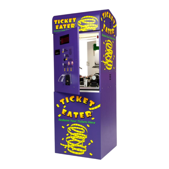
The TT-2000 Ticket Eatera
A fully automated, high speed, stand alone Ticket Eater
that counts and destroys tickets and prints a receipt.
TT-2000
Only 21"L
x
x
A valuable tool to make the redemption process part
FUN!
of the
The customers feed their own tickets into
the
'IT-2000
and enjoy the display and counting process
presenting a receipt to redeen~ their prizes.
High visibility five digit 2 LED display of each ticket
value and total points countetl-
FULL
PRINT
User friendly ,Thertnal Printer forhst, Crisp
print-outs. (Accepts up to
Programmed when matlufactured to accept and
ONLY
read
your custom bar coded tickets.
OPTION: Can read tlon bar coded ticltets
Can be programtned on location to read up to eight
different bar coded ticket values
Accepts standard redemption ticltets
4 blades in one means, extremely long life!!!
No cheating allowed!!! Pull on those tickets
and it subtracts one!
Interfaces available for popiilar debit card systems.
Can be interfaced with existing vending machines
to create Fully automated redemption.
For fu~ther detalls and specs on the excitlng
please call
Patents 521
U.S.
Another quality p r ~ d u c t from Deltronic Labs.
8
to 10 ticlets/sec
PAPER low
ERROR
8"
paper roll)
SALES at 215-997-8616
5996457
1093
For information on our complete line of products, please
Liberty
120
Visit us of our web site: w~.deltroniclobs.com
. .
x
. .
the industry leader in ticket dispensers
Lane,
Chalfonf, P A
Available
3Amp
.
4
Advertisement

Related Manuals for Deltronic Labs Ticket Eater TT-2000


Summary of Contents for Deltronic Labs Ticket Eater TT-2000
- Page 1 SALES at 215-997-8616 please call Patents 521 5996457 U.S. 1093 Another quality p r ~ d u c t from Deltronic Labs. the industry leader in ticket dispensers For information on our complete line of products, please Lane, Liberty Chalfonf, P A...
- Page 2 TABLE OF CONTENTS General Operation Procedures Printers Thermal (CITIZEN) Dot Matrix (STAR) Entry of Options Date Time Receipt Options Machine Codes Setting Full Bucket Security Levels Paper Length Indicator ("PAPEr") Entering Bar Codes Re-setting Counters, Options and Audits Printer Paper Loading Maintenance Check List Trouble Shooting Detail of Parts...
- Page 3 TT-2000 OPERATING PROCEDURE3 REVS. 24M, 24T, 25T & Rev. 3.1 -7T, M& K Two switches (red and blacklwhite) are located inside the unit. These switches are on the left side of the lower shelf near the mechanism. The blacklwlute switch is wired to the front switch.
- Page 4 Note that the display (on the front door) now reads '99 0'. Press and release the black switch to change the '0' to '1' and then to '2' to '3' and the display will display '0' then '3' then '2' then '1' and then back to '0'. This fact will also be used to set a value.
- Page 5 The display should read "7" plus a flashing number, which is the "minute". Change to read '24'. Press both switches when done. Value can be set from 0-59. At this time, the seconds are set to '0' OPTIONS While in the setup mode, the display will read '99 0'. Increment the display to read '99 1'.
- Page 6 (CONTINUED): example, if you want the machine number to be '123' set this value to 1. Press the two switches at the same time when done. (Note: This is the FIRST digit in the barcode printed on the receipt if the check suill option is disabled.
- Page 7 The display will now sl~ow '27nn' (nn=O to 17). This sets the percentage of good tickets versus bad tickets that the unit will accept from a strip of tickets. The chart below shows an example of percentages available: NOTE: Effective for bar-coded tickets ONLY. Value Good Value...
-
Page 8: Re-Set Counters
Wliile in the setup mode, the display will read '99 0'. Incretne~it the display to read '99 3'. Press both switches at this time to learo new bar codes as follows: ticket. Pressing and releasing both switches will cause the display to go to ' 3 21111' etc. - Page 9 For use \\,it11 TT-2000 Ticket Eater purchased after 6-15-2003. Unit contains a 5 digit LED display ATTENTION: Functions and features of V2R7(.2)K Software The V2R7K software uses slightly different commands and functions then prior revisions. These differences are listed below. (See yellow label on prom for Rev. number) The "Functions"...
- Page 10 PAGE 7...
- Page 11 For 7" to 8" paper roll, the low indicator is set to 1150 ft. For a 4 112" roll, it is set 485 These lengths are approximate and the settings can be changed in the field. Refer to operating instructions or call Deltronic Labs at (215) 997-8616. PAGE 8...
- Page 12 TT- 1000 TT-2000 When the guide assembly is released or entire assenlbly is removed IMPORTANT: The MOTOR assenlbly has extra "0" rings installed on both Lower drive roller and motor shafts. Before replacing GUIDE assembly, be sure the rings are not "riding" on the sides of the rollers. They should be far left or right of Roller ends, towards side plates.
- Page 13 Carefully remove cable from top of PCB. Remove (2) thumb screws. Lift PCB straight up, and tusn over. Using a soft cloth or alcohol swab, carefully wipe optos. Replace PCB, thumb screws and cable. Clean rear fan filter (located behind cabinet )when applicable. Remove filter frame under fan by pulling down on sides of frame.
- Page 14 OFF. Do not use a inetal end vacuum to clean any PCB's. A can of Do not bloclr exhaust fan on rear and right side of unit. If placing near switch. If bin is einptied erratically the full co~unt will be disrupted. If trash disposal is scheduled otherwise, i s .
- Page 15 There Diagnostie LED'S TT-2000 Tray Status Logic Bonrcl Rev5 -Both normally ON Red L.E.D. *If OFF, check power Green L.E.D. switch, 2.25AMP SB Fuse connections Barcode Reader BorcrcE Indicates Status (HO-1000 PCB) Version 2 Rev. I& UP Ticket Detect -Normally ON Front Red L.E.D.
- Page 16 TROUBLE SHOOTING FLOWCHART OPEN DOOR AND POWER ON BY PULLING OUT THE WHITE INTERLOCK SWITCH Red toggle switch supplies power to the Printer, Motor Assembly & Logic PCB On the Logic Board is the Check power sw, 5A & 2.25A S.B. fuse. Red and Green L.E.D.
- Page 17 Check: Front sensor positioning & Does the motor run before inserting leads & drive transistor. Power tickets (At power-up)? Supply for 5V to Barcode PCB. Blocked Entrance block. Power off the TT-2000 and remove the Cutter reposition. Re-test. Remove cutter, check: A.
- Page 18 SCALE SAMPLE OF CORRECT ROLLER SPRING SHAPE AS REMOVED FROM ASSEMBLY NOTE: REAR PINS PLATE SPRINGS CAUTION! W E N INSERTING GUIDE ASSEMBLY INTO GUIDE HOUSING ASSEMBLY, YOU MUST ALIGN M E TOP ROLLER SHAFTS IN THE APPROPRIATE SLOTS BEFORE PUSHING THE GUIDE ASSEMBLY DOWN AND FORWARD.
- Page 21 OATE PG. 18...
- Page 22 NOTE: ITEMS 16 (THUMB SCREWS) AND ARE NOT INCLUDED IN ASSEMBLY. DATE TICKET EATER GUIDE ASSEIABLY EXPLODED t' I EVl...
- Page 23 TE IDLER ROLLER SHAFT BRNG-F3 IZ/TT/BRAS FLANGED BRONZE BEARING EXPLODED VIEW ROLR- IDLERITE DRAWN 2/2/00 PG. 20...
- Page 24 Bar code Reader PCB). correctly. If you have ally difficulty selecting these nlodes or options, please contact Deltronic Labs at (2 15) 997-86 16. NOTE: revision as annotated on the yellow label on the main chip on the logic board. The Barcode board is Rev.8 or Version 2 Rev 1 6c up and the logic...
- Page 25 Stationary Blade Adjustment The TICKET EATER blade is adjusted at the factory. Blade wear will occur over time. Adjusting the blade so that it is closer to the cutter will extend the life FIGURE of the blade. Follow these simple steps: Step Turning the set screw Step 1.
- Page 26 Stationary Blade Replacement the position of the beveled edge and take care not to install the blade The TICKET EATER blade has two backwards. If both edges of the blade cutting edges. When one edge are worn, replace blade. becomes dull and cannot be adjusted any further, it can be flipped around to use the second edge.
- Page 27 CLAMP SCREW) OUTPUT IMPORTANT! MOTOR DRIVE CLUTCH Clamp PART Disks CLUTCH FOR T T 2 0 0 0 Partially tighten.one screw, then the othcr. BE SURE there is equal distance between top and bottom portions of clamp when both screws are tight. (SEE DRAWING) aligned properly when clutch is inserted.
- Page 28 NOTE: For HO- 1000 Rev.4 OP2 Position l,OP3 Position 2 For BCR-1000 Rev.3 OP1, Use Position 1 or 2 For Ticket guide assemblies with OVAL cutouts use Position 1 or 2. For Ticket guide assemblies with ROUND cutouts use: Position 1 ONLY. (Middle Sensors Only) IMPORTANT: For Sensor Replacement: Scanner PCB's BCR-1000 Rev.
- Page 29 f o r only opero.tion. BCR 100 The r o n f i ~ u r a t ~ o n above is f o r holes barcodes. Above a r e t h e d i f f e r e n t configurations f o r t h e 8CR1000 t i c k e t r e a d e r PCB. different r e v s , a r e shown (V2R1 &...
- Page 30 TTEX AC HARNESS STANDARD & DKS VERSION NOTE: WIRE COVERS ARE CLEAR EXCEPT WERE NOTED SWITCH UNDER SHELF POWER SUPPLY MOO. GLC750 PAGE 27...
Need help?
Do you have a question about the Ticket Eater TT-2000 and is the answer not in the manual?
Questions and answers