
Related Manuals for Wildlife Acoustics SMART MIC-1


Summary of Contents for Wildlife Acoustics SMART MIC-1
- Page 1 See Page 1 for Quick Start Guide SMART Song Meter with Analysis and Remote Transfer User Guide Last updated on 04/22/2022...
-
Page 2: Table Of Contents
Ultrasonic Speaker ............................. 10 Heater ................................ 10 RJ45 Weatherproofing and Ferrite Kit ......................10 RJ45 Surge Protector ..........................14 Example SMART MIC-1 Configurations ....................... 15 5 SMART Web Interface Connect To The SMART Web Interface ....................... 17 Devices Tab ..............................18 Data Files Tab ............................. - Page 3 Visit www.wildlifeacoustics.com/support/tutorial-videos to view tutorial videos for the SMART System. Technical Support For technical queries contact the Wildlife Acoustics support team: https://www.wildlifeacoustics.com/contact-us North America (toll-free): 1-888-733-0200 Outside North America (toll charges may apply): +1 978-369-5225 Don’t miss out on Important Updates We continually add features to the SMART System.
-
Page 4: Quick Start Guide
The default password is “wildlife”. ■ The SMART Web Interface will now be displayed. All user functions of the SMART System, including any connected SMART MIC-1 microphone devices, are now accessible. ■ SMART Controller is WIFI HotSpot (Default configuration) Wildlife Acoustics, Inc. -
Page 5: Overview
The SMART System can be updated by downloading and applying a software package update file. ■ The SMART System update may or may not include a firmware update for the SMART MIC-1 Device (Or other Device models in ■ the future). -
Page 6: Smart Controller
Other power sources can be used for the SMART Controller as long as they meet the specified requirements. ■ Actual power consumption will vary based on attached peripherals, CPU load, system configuration, and other factors. ■ Wildlife Acoustics, Inc. page 5... -
Page 7: Smart Controller Processing Limitations
NOTE: If these limitations are exceeded, there may be drop-outs in the recordings (e.g. missing time and phase discontinuities). Grounding When the SMART Controller is deployed it should be properly grounded. ■ Use the Grounding Lug to connect the SMART Controller to a secure ground point. ■ Wildlife Acoustics, Inc. page 6... - Page 8 Power Button and status USB 3.0 X4 (Blue when powered on) Grounding Lug Antenna Antenna connection 2X RS-232/422/485 Power Connection connection Serial connection Display Ports RJ45 GbE RJ45 2X GbE LAN Switch (Ethernet) with PoE (Devices) Wildlife Acoustics, Inc. page 7...
-
Page 9: Smart Mic-1
Is powered over Ethernet (PoE) either by direct connection to the SMART Controller or from a PoE switch or injector. ■ Communicates with the SMART Controller using an Ethernet protocol developed by Wildlife Acoustics. This protocol features: ■ Automatic discovery... -
Page 10: Enclosure And Mounting
Mounting The SMART MIC-1 Is designed to be mounted using a standard metal clamp. Any type of clamp can be used as long as it makes connection with the grounding strip on the SMART MIC-1 enclosure. ■ The metal clamp should then be connected to a ground point. -
Page 11: Ultrasonic Speaker
The SMART MIC-1 has a sensitivity calibration system which can test each Ultrasonic Sensor and automatically switch to the sensor with the best test result. The Ultrasonic Sensors have a cardioid pickup pattern, therefore the front of the SMART MIC-1 should be pointed towards the ■... - Page 12 SMART User Guide SMART MIC-1 Make sure the CAT5/6 cable fits through the End Collar. For a commercial cable, it may be necessary to carefully cut the cover off from around the actual RJ45 connector. Cover removed Will not fit Thread the CAT5/6 cable through the End Collar.
- Page 13 SMART User Guide SMART MIC-1 Push the End Collar onto the Connector Body and then turn to tighten. The threaded End Collar will screw on to the Connector Body and tighten against Waterproof Grommet to create a seal. Push on...
- Page 14 Attach the second zip-tie to secure the Ferrite in place. NOTE: The Ferrite must be connected to the end of the cable which connects to the SMART MIC-1, and must be as close as possible to the connector. The CAT5/6 cable is now connected to the RJ45 port of the SMART MIC-1. The Integrated Screw-On Collar has been turned and tightened to provide a secure and waterproof connection.
-
Page 15: Rj45 Surge Protector
The Surge Protector is used to help protect the next device in line from electrical charges, such as nearby lightning. ■ The Surge Protector must be connected to the opposite end of the CAT5/6 cable which connects the SMART MIC-1 to either ■... -
Page 16: Example Smart Mic-1 Configurations
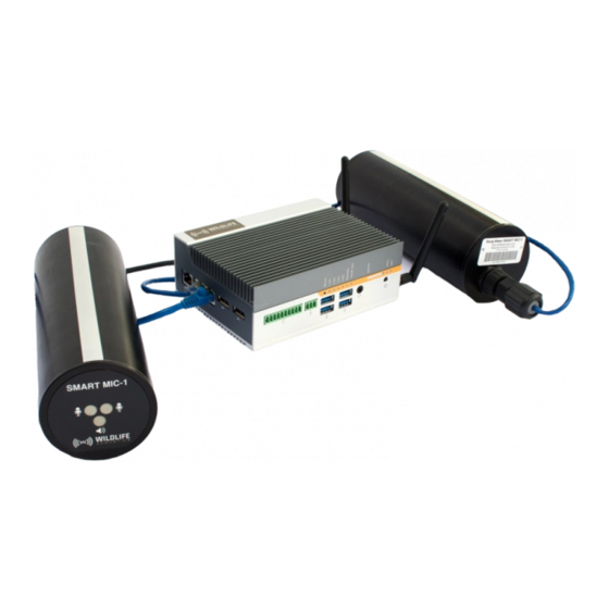
The following are graphic descriptions of three possible configurations of SMART MIC-1 microphone systems and a single SMART Controller. A PoE switch can be used to extend range and provide power for one to three SMART MIC-1 microphones. ■ An RJ45 Surge Protector is always used with the CAT5/6 cable connected to the SMART MIC-1. - Page 17 • Grounded surge protector • Grounded SMART Controller • Three SMART MIC-1 Devices Connected to PoE Switch and SMART Controller Each SMART MIC-1 connects to: Grounded metal mounting bracket One to three SMART MIC-1 devices can then connect to: •...
-
Page 18: Smart Web Interface
The SMART system will prompt for a System Name, and the password. ■ Once logged in, the SMART web browser interface will be displayed. ■ The Browser Interface will display the current SMART system name Wildlife Acoustics, Inc. page 17... -
Page 19: Devices Tab
Menus Device from List Add Or Delete A Device Connect an Ethernet cable from the Device (SMART MIC-1) to one of the two PoE RJ45 ports on the SMART Controller. (either ■ directly or via a PoE switch or injector). - Page 20 The currently installed firmware version of the SMART MIC-1 Device is displayed. ■ If a new firmware update is available for the SMART MIC-1, an update button will be displayed under the Device tab, when the ■ SMART MIC-1 is Idle.
-
Page 21: Data Files Tab
All Devices which have ever been connected to this SMART Controller are listed here. ■ This includes Devices which may have been deleted from the Devices tab. Select one or more Devices to include data from those Devices. Wildlife Acoustics, Inc. page 20... -
Page 22: Settings Profiles Tab
The Settings Profiles tab provides functions for creating and saving Device configurations. ■ Individual Settings Profiles can be recalled and assigned to a Device under the Devices tab. ■ Kaleidoscope Pro software is built into the SMART System. Kaleidoscope Pro provides real-time analysis functions. ■ Wildlife Acoustics, Inc. page 21... - Page 23 The front plate of the SMART MIC-1 has a built-in heating element. ■ The Heater will increase the temperature of the front plate of the SMART MIC-1 to roughly 20ºC above ambient temperature. ■ The purpose of the is to clear condensation from the Ultrasonic Sensors.
- Page 24 This specifies how long the Calibration will be activated within the Schedule Profile Schedule Block. If no Calibration Period is specified, the Calibration will not be activated by this Device Profile. Values: Not Specified, 1 – (no upper limit but determined by schedule block duration) Wildlife Acoustics, Inc. page 23...
- Page 25 Values: On/Off Default: On (Checked) Output WAV This checkbox determines whether .wav files will be recorded when the SMART MIC-1 streams audio to the SMART Controller. Creation of .wav files is subject to trigger parameters ■ Creation of .wav files is further based on the current Schedule Profile.
- Page 26 Values: None, W4V-8, W4V-6, or W4V-4 Default: None Output ZC This checkbox determines whether .zc files (Zero Crossing) will be recorded when the SMART MIC-1 streams audio to the SMART Controller. Recording of .zc files is subject to trigger parameters ■...
- Page 27 Minimum number of pulses Specify the minimum number of pulses required to consider a signal a bat. If the minimum number of pulses is not met in a triggered recording, the recording will be marked as NOISE. ■ Wildlife Acoustics, Inc. page 26...
-
Page 28: Schedule Profiles Tab
Classifier A Classifier is used to narrow the species choice available to the Auto-ID process. Select the appropriate classifier and region for the location of the SMART MIC-1. ■ When a region has been selected, species are pre-selected according to Bat Conservation International recommendations ■... - Page 29 If Hours and Minutes are both left at 00, the End time will be exactly at sunrise or sunset each day. If a value is entered into the Hours and/or Minutes fields, the Schedule Block will cease at Sunrise or Sunset, plus or minus the specified Hours and/or Minutes Wildlife Acoustics, Inc. page 28...
- Page 30 ■ End is set to Sunrise ■ Sunset and Sunrise times are automatically calculated based on date and location ■ This Schedule Block will record from Sunset to Sunrise per each 24 hour period. ■ Wildlife Acoustics, Inc. page 29...
- Page 31 The first Schedule Block is set to run continuously from one hour before sunset to two hours after sunset. ■ The second Schedule Block is set to run continuously from two hours before sunrise to one hour after sunrise. ■ Wildlife Acoustics, Inc. page 30...
-
Page 32: Time And Location Tab
■ If the SMART System will be connected to a public IP network, this is preferred. ■ Otherwise, to manually set the date and time, the automatic time synchronization service must first be disabled. ■ Wildlife Acoustics, Inc. page 31... -
Page 33: Serial Output Tab
As analysis results are generated by the Device(s) streams, the selected columns will be output to the serial port with specified ■ text at the beginning and end of each line. Press the Apply Changes button to update the SMART System with the current Serial Output settings. ■ Wildlife Acoustics, Inc. page 32... -
Page 34: Networking Tab
SMART Controller to the default netplan. For command-line instructions for resetting the default netplan, check Additional Resources. Basic/Advanced Network Configuration The Networking tab provides two views for editing settings. The following section describes the Basic Network Configuration view. Wildlife Acoustics, Inc. page 33... - Page 35 SMART Controller's WiFi to client mode (and connect to a different WiFi network), or disable the SMART Controller WiFi completely. NOTE: The SMART System requires a DNS server if the Wildlife Acoustics gateway feature is being used to lookup and connect to the gateway’s IP address.
- Page 36 NOTE: The default DHCP server settings are matched with the default WIFI network settings. Specifically, the subnet IP address is 192.168.19.0, the netmask is 255.255.255.0, the default route is 192.168.19.1, and the range of addresses available to allocate to clients is 192.168.19.128 to 192.168.19.192. Wildlife Acoustics, Inc. page 35...
- Page 37 SMART User Guide SMART Web Interface Interface Status Current status of all network functions are displayed. Wildlife Acoustics, Inc. page 36...
-
Page 38: Maintenance Tab
Set the Hour and Minute each day when the SMART System will enter Maintenance mode. After maintenance, power down until Set the Hour and Minute each day when the SMART System will power back on. Copy data to external USB drive if available Wildlife Acoustics, Inc. page 37... - Page 39 CSV files and log files, as well as WAV/W4V and ZC files, can be automatically deleted after a specified number of days. Values: Not Specified Default: 365 Email Configuration A summary report is generated for each maintenance mode session. Wildlife Acoustics, Inc. page 38...
- Page 40 Finished daily maintenance at 2020-12-28 05:12:16 (735 seconds) Sleeping until 06:30 Apply Changes Press the Apply Changes button to update the SMART System with the current Maintainence settings. Public ssh key for user www-data (provided here for convenience) Wildlife Acoustics, Inc. page 39...
-
Page 41: Administration Tab
All authorized users with access to the SMART System have access to the Administration functions. Unix and Web Password for ‘smart’ The default password is “wildlife”. To change the default password: Enter Password Enter Password (again) Press: Change Password SMART System Name The default SMART System name is “smart”. Wildlife Acoustics, Inc. page 40... - Page 42 A SMART System update may or may not include a SMART MIC-1 firmware update. If the SMART System update does include a SMART MIC-1 firmware update, an Update button will be available next to the ■...
-
Page 43: Connection To The Smart System
■ NOTE: If the netplan is applied incorrectly, the SMART System may become inaccessible via WIFI or Ethernet connection. If this happens the default netplan can be restored directly via command-line. Wildlife Acoustics, Inc. page 42... -
Page 44: Wifi
SMART System tablet) SMART Web Interface SMART Controller is WIFI network client (requires netplan configuration) SMART Controller WIFI Router WIFI SMART System WIFI or Ethernet Device (Laptop, PC, WIFI or smartphone, tablet) Ethernet SMART Web Interface Wildlife Acoustics, Inc. page 43... -
Page 45: Rj45 Ethernet
RJ45 Port number 1 is used for Ethernet connection of the SMART Controller. ■ RJ45 PoE Ports numbers 2 and 3 are used for connection to one or more Devices, such as the SMART MIC-1. ■ The default netplan sets up the Ethernet port to acquire its configuration via DHCP. -
Page 46: Smart Internet Gateway
When the Internet Gateway function is enabled, the SMART System will create an encrypted connection to a secure Internet ■ Gateway service operated by Wildlife Acoustics. The Internet Gateway service uses encrypted communication and can be restricted to specific IP addresses for maximum ■... -
Page 47: Configure The Smart System For Internet Gateway Connection
Under Wildlife Acoustics IOT Gateway, enter (or delete) the Wildlife Acoustics account email addresses of the users who will be authorized to have access to the SMART Controller. NOTE: Each authorized user to have access to the SMART System must have a Wildlife Acoustics web account. A Wildlife Acoustics web account can be created here: https://www.wildlifeacoustics.com/account/login... -
Page 48: Configure Gateway Access Through Wildlifeacoustics.com
For each authorized user, there will now be a SMART Gateway tab on the left. If there is no SMART Gateway tab in the user account, this means the Wildlife Acoustics managed gateway has not received authorization for that user account from the SMART System. - Page 49 Enter the SMART System username and password (Default user name is “smart”. Default password is “wildlife”) The browser may display messages about not trusting the SSL/TLS certificate or other security concerns. Connect anyway. This is a secure connection. The SMART Web Interface will now open. Wildlife Acoustics, Inc. page 48...
-
Page 50: Network Security
For example, it is possible to connect to a VPN with a private static IP and access the SMART Controller from other authorized VPN clients. The SMART System does not require the Wildlife Acoustics IOT gateway. ■... -
Page 51: Smart Controller Dimensions
Streaming and analyzing two microphones: 12.2 W Streaming/ analyzing one microphone, heater enabled: 15.2 W Streaming/analyzing two microphones, heaters enabled: 17.9 W SMART MIC-1 Ultrasonic Microphone Dimensions Length: 8.9 inches (226 mm) Diameter: 3.0 inches (76 mm) Weight: 1.4 pounds (0.64 kg) Operating Temperature: -4°F to 185°F (-20°C to 85°C) -
Page 52: Smart Mic-1 Audio Specifications
SMART User Guide Specifications SMART MIC-1 Audio Specifications Ultrasonic Sensors: 2, recordings made from strongest sensor Ultrasonic Speaker: 40 kHz test tone Condensation/ice Heater: 20ºC above ambient temperature Recording Format: 16-bit PCM WAV Supported Sample Rates (kHz): 256, 384, and 500... -
Page 53: Additional Resources
Change the mode for Serial Port 1 (ttyS0) or Serial Port 2 (ttyS1) from RS-232 to RS-422 (with or without termination resistor) and RS-485 (with or without termination resistor). Bat Analysis Statistics When Bat Analysis/Triggering is enabled, the SMART System uses Kaleidoscope Pro to generate statistics per event (bat pass). Wildlife Acoustics, Inc. page 52... -
Page 54: Terms Of Use
The following statistics are available in results.csv files and real-time serial output. Prefix This is the serial number or customized name of the SMART MIC-1 Device which has made the detection. ■ Date Date of the event. -
Page 55: Warranty And Disclosures
Wildlife Acoustics, Inc. Limited Warranty HARDWARE: Wildlife Acoustics, Inc. (“WAI”) warrants to the original end user (“Customer”) that new WAI branded products will be free from defects in workmanship and materials, under normal use. Refer to the Hardware Limited Warranty table at the top of this page for the applicable warranty period from the original date of purchase. - Page 56 In no event shall Wildlife Acoustics, publishers, authors, or editors of this guide be liable for any loss of profit or any other commercial damage caused or alleged to have been caused directly or indirectly by this...
Need help?
Do you have a question about the SMART MIC-1 and is the answer not in the manual?
Questions and answers