
Subscribe to Our Youtube Channel
Related Manuals for Gas Clip Technologies Infrared


Summary of Contents for Gas Clip Technologies Infrared
- Page 1 Multi Gas Clip Pump Multi Gas Clip Pump Infrared Pellistor User’s Manual...
-
Page 2: Table Of Contents
MGC Pump User’s Manual CONTENTS Warning Statements . . . . . . . . . . . . . . . . . . . . . . . . . . . . . . . . . . . . . . . . . . . . . . . . . . . . . . . . . . . . . . . . . . . . . . . . . . . . . READ FIRST BEFORE OPERATION . -
Page 3: Warning Statements
Do not substitute components as this may interfere with the intrinsic safety of the device. DO NOT substitute any other battery type than specified and supplied by Gas Clip Technologies. Only use Gas Clip Technologies chargers and parts in the detector. Unapproved parts will void the warranty and are considered unsafe. - Page 4 Ne remplacez pas les composants car cela pourrait interférer avec la sécurité intrinsèque de l’appareil. NE PAS substituer un autre type de batterie que celui spécifié et fourni par Gas Clip Technologies. Utilisez uniquement des chargeurs et des pièces Gas Clip Technologies dans le détecteur. Les pièces non approuvées annuleront la garantie et sont considérées comme dangereuses.
-
Page 5: Detector Components
MGC Pump User’s Manual DETECTOR COMPONENTS Entry Description Power Button Audible Port Display Alarm Bar LEDs Maintenance LEDs IR Communication Window Gas Inlet Filter Window Certification Label Model and Serial Number Gas Exhaust Charging Port Alligator Clip with Safety Ring UM-MGC-P v1.06 3 of 19... -
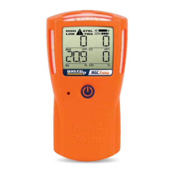
Page 6: Display Components
MGC Pump User’s Manual DISPLAY COMPONENTS Display Layout Entry Description Alarm Condition Pump Status Calibration/Test Mode Battery Charge Level Gas Readings Gas Identifiers Display Details • When a gas is reading at, or above, its alarm thresholds, the gas identifier icon will flash and the associated alarm condition icon will display. -
Page 7: Alarms
MGC Pump User’s Manual ALARM Default Alarms Each detector comes preprogrammed with the factory default settings below for Low, High, Time Weighted Average (TWA) and Short Term Exposure Limit (STEL) alarms. Sensor High STEL 10 ppm 15 ppm 10 ppm 15 ppm 35 ppm 200 ppm... -
Page 8: Basic Operation
MGC Pump User’s Manual BASIC OPERATION Button Usage Operation of the detector is driven by a single button located on the front of the detector as described below: • Turn On/Off • Menu Navigation (Status and Options) • Latched and Pump Alarm acknowledgement •... -
Page 9: Detector Records/Logs
MGC Pump User’s Manual DETECTOR RECORDS (LOGS) During operation, the detector records all usage activity. These records can be downloaded from the detector via the IR Link software and an IR Link or from the MGC Pump Dock. The Event, Bump and Calibration Logs are always downloaded. The user may also choose to download different amounts of the data log to reduce the transfer time. -
Page 10: How To Retrieve Logs Using The Gct Ir Link
MGC Pump User’s Manual How to Retrieve Data Logs Using the GCT IR Link *You must have Microsoft Excel to open Data and/or Event Logs *Computer System Requirements: Available for Windows© based PCs (Vista, 7, 8.x, 10) *Browser requirements: Google Chrome, Firefox, Opera or Edge Set the detector in front of the GCT IR Link with the GCT IR Link Communication Window and MGC Pump Commu- nication Window lined up approximately 2-3 inches apart. -
Page 11: Detector Options/Menus
MGC Pump User’s Manual DETECTOR OPTIONS/MENUS To access the user menus, press the button two separate times in quick succession (double-tap). The detector will display: • Current date/time • User-programmed text message • Status menu prompt • Options menu prompt If the Status Menu is accessed by pressing the button during the prompt, the detector will display: •... - Page 12 MGC Pump User’s Manual Maintenance Notification- If maintenance notification is enabled, the detector will periodically flash the maintenance LED. Otherwise, if the option is disabled, the detector will only show the maintenance text on the display. Pump Test- Will require the pump to be tested (block and unblock) on startup. Dock Lock- Dock Lock prevents calibrations and bump tests without the use of the IR Link or the MGC Pump Dock.
-
Page 13: Main Menu
MGC Pump User’s Manual Activity LED Period – This option periodically flashes a single LED on the detector at a rate specified by the user to indicate that the detector is on. The time between flashes can be set and adjusted through the GCT IR Link software or GCT Manager software. -
Page 14: Detector Maintenance
MGC Pump User’s Manual DETECTOR MAINTENANCE Applying Gas from a Gas Cylinder The detector contains an internal pump that is continually drawing in gas through the gas inlet. The best way to apply gas from a cylinder is through the use of a demand flow (vacuum-actuated) regulator. This type of regulator will supply the exact amount of gas that the detector is drawing with the pump. -
Page 15: Bump Testing
MGC Pump User’s Manual Bump Testing The detector can be configured to keep track of regular bump testing intervals. When the detector has exceeded the bump interval, it will display “BUMP DUE” until it has been successfully bump tested. To bump test the detector, either insert the detector into the MGC Pump Dock, or manually apply gas from the bump test screen described below. -
Page 16: Filter Replacement
MGC Pump User’s Manual The detector will first automatically zero the sensors at the current baseline reading, then the detector will prompt to "APPLY GAS." Once the screen displays “APPLY GAS”, apply gas to the detector’s gas inlet. As the detector detects gas, the sensor readings will be displayed and adjusted throughout the calibration. -
Page 17: Accessories And Replacement Parts
- Also available in a Hi-Pressure version. GCT IR Link: (P/N: GCT-IR-LINK) - Infrared communications device and USB cable used for communications be- tween detector and computer to easily make firmware updates, adjust detector settings and record data. - Page 18 MGC Pump User’s Manual LCD Screen: (P/N: MGC-P-LCD) - Replacement LCD screen Printed Circuit Board (PCB): (P/N: MCG-PUMP-PCB) - replacement circuit board Battery: (P/N: MGC-BAT) - replacement battery Internal Pump Motor: (P/N: MGC-PUMP-MOTOR) - replacement internal pump motor Replacement Particulate Filters: (P/N: MGC-PFILTER-10 and MGC-PFILTER-50) - replacement particulate (hard plastic) filters in either a 10 pack or a 50 pack.
-
Page 19: Detector Specifications
S, CO, O : Single plug-in electrochemical cell Sensor Type Combustible: Plug-in infrared (IR) or pellistor User Message, Language, Low Alarm, High Alarm, STEL Alarm, TWA Alarm, TWA Method, TWA User Options Interval, STEL Interval, SAFE, Maintenance Notification, Self-test Lock, Dock Lock, Pump Test, Sensor Enable, Calibration Interval, Bump Interval, Calibration Gas UM-MGC-P v1.06... - Page 20 MGC Pump User’s Manual DETECTOR SPECIFICATIONS Approvals MGC-IR-PUMP MGC-P-PUMP CSA 14.2696027 CSA 14.2696027 Intrinsically Safe/Sécurité lntrinsèque Intrinsically Safe/Sécurité lntrinsèque Class I, Division 1, Groups A, B, C and D, T4 Class I, Division 1, Groups A, B, C and D, T4 Ex ia IIC T4 Ga Class I, Zone 1, AEx d ia IIC T4 Gb Class I, Zone 0, AEx ia IIC T4 Ga...
-
Page 21: Limited Warranty
LIMITED WARRANTY Gas Clip Technologies (“GCT”) warrants this product to be free from defects in material and workmanship under normal use and service for a period of two years beginning upon the date of activation for all Multi Gas Clip products. Date of activation allowance is limited to the “Activate before…”...
Need help?
Do you have a question about the Infrared and is the answer not in the manual?
Questions and answers