Table of Contents
Advertisement
Quick Links
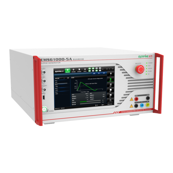
EMS61000-5A
SURGE GENERATOR
USER'S MANUAL
Ver 6.03
EVERFINE Corporation (Stock Code: 300306)
ADD : Bldg.1 #669 Binkang Rd., Binjiang Hi-Tech
Zone, Hangzhou(310053), China
Tel :86-571-86698333
Fax :86-571-86696433
E-mail:Global@everfine.net
Globalservice@everfine.net
http://www.everfine.net
Copyright © EVERFINE, Copy or spread without authorization is prohibited.
Advertisement
Table of Contents

Related Manuals for Everfine EMS61000-5A

Summary of Contents for Everfine EMS61000-5A
- Page 1 EMS61000-5A SURGE GENERATOR USER’S MANUAL Ver 6.03 EVERFINE Corporation (Stock Code: 300306) ADD : Bldg.1 #669 Binkang Rd., Binjiang Hi-Tech Zone, Hangzhou(310053), China Tel :86-571-86698333 Fax :86-571-86696433 E-mail:Global@everfine.net Globalservice@everfine.net http://www.everfine.net Copyright © EVERFINE, Copy or spread without authorization is prohibited.
-
Page 2: Foreword
Warm notice to valued customers of EVERFINE "Ensure the quality, insist on continuous improvement and make every customer more satisfied" is the quality policy of EVERFINE. Therefore, the quality of products and services provided by EVERFINE should be better than those have been promised. -
Page 3: Copyright Statement
EVERFINE. Any infringement related above can be traced back to the responsible user by the unique product number printed in the manual. If EVERFINE has signed a written agreement with user and the contents in the agreement are in conflict with above terms, the contents in the written agreement have preferential force effect. -
Page 4: Safety Previsions
If the instrument is used in the manner not specified in this manual, the function of this instrument may be hindered. This instrument adopts the following safety symbol. Electric shock High voltage Grounding Copyright © EVERFINE, Copy or spread without authorization is prohibited. - Page 5 Don't operate the instrument when the hand is wet or the relative humidity is too high. Transportation Please be careful when delivering the instrument to avoid collision, inversion and vibration. Copyright © EVERFINE, Copy or spread without authorization is prohibited.
-
Page 6: Cautions
L-phase is not equal to the current flowing through the N-phase. Ampere of current will cause the circuit with leakage protector to trip. The customer should take corresponding measures. Copyright © EVERFINE, Copy or spread without authorization is prohibited. -
Page 7: Table Of Contents
4.1.3 "Test Report" interface................18 4.1.4 "Library" interface.................21 4.1.5 “Help”interface................22 4.1.6 Test step area..................24 4.1.7 Parameter setting area................25 4.1.8 Parameters of the cruise.................29 4.1.9 Dynamic display area................30 Copyright © EVERFINE, Copy or spread without authorization is prohibited. - Page 8 6.4.1 Direct output terminal voltage waveform test........38 6.4.2 CWG direct output short circuit current test......... 39 6.4.3 CWG open circuit voltage waveform test at coupling end....40 6.4.4 Test the coupling end short circuit current waveform......40 Copyright © EVERFINE, Copy or spread without authorization is prohibited.
-
Page 9: Chapter 1 Overviews
EMS61000-5A User’s Manual Chapter 1 Overviews EMS61000-5A lightning surge generator is a high reliability test system specially designed for the characteristics and requirements of lightning surge immunity test in electromagnetic compatibility test. The equipment can simulate lightning strike, produce high energy (high voltage, high current) surge, can realize 1.2/50μs (8/20μs), pulse magnetic field test multi-function automatic switch, high intelligence degree, easy to use. -
Page 10: Chapter 2 Specifications
Repetition rate 10-9999s 2Ω/12Ω Polarity positive/negative/alt Cruise Voltage/phase parameters Instrument power supply Alternating current 100-240VAC(50Hz/60Hz) 2.2 Built-in 1phase CDN The maximum capability of the EUT source: maximum allowable durative current Copyright © EVERFINE, Copy or spread without authorization is prohibited. -
Page 11: Definition Of Output Waveform
Table1 1.2/50μs CWG Open-circuit voltage parameter coupled mode Front timeT =1.67T Duration T Direct output/ 1.2µs±0.36µs 50µs+10µs/-15µs line-to-line coupling line-to-ground coupling 1.2µs±0.36µs 50µs +10µs/-30µs Fig2.1 1.2/50μs CWG waveform of the surge voltage Copyright © EVERFINE, Copy or spread without authorization is prohibited. -
Page 12: Pulse Magnetic Current Waveform
1.2/50μs CWG waveform of surge current 2.3.2 Pulse magnetic current waveform Table3 Pulse magnetic field current waveform parameters coupled mode Front timeT1 duration T2 direct output 6.4µs±1.92µs 16µs±4.8µs Fig2.3 Pulse magnetic current waveform Copyright © EVERFINE, Copy or spread without authorization is prohibited. -
Page 13: Conventional Technical Index
EMS61000-5A User’s Manual 2.4 Conventional technical index Environment temperature:15℃~35℃ Relative humidity:25%~75% Atmospheric pressure:86kPa~106kPa Power voltage:AC 100V~240V Power frequency:50Hz/60Hz±1% Volume(W×H×D):480mm×226mm×500mm Weight: about 38kg Copyright © EVERFINE, Copy or spread without authorization is prohibited. -
Page 14: Chapter 3 Panel Shows
EMS61000-5A User’s Manual Chapter 3 Panel shows 3.1 Front panel Fig3.1 Front panel fig of the EMS61000-5A surge generator Pulse voltage monitor BNC U-CRO:1000/1(±20%) I-CRO: 500A/V(±20%) Pulse current monitor BNC Trigger out 5V TTL Import and export test procedures and reports,... -
Page 15: Rear Panel
EMS61000-5A User’s Manual 3.2 Rear panel Fig 3.2 Rear panel fig of EMS61000-5A surge generator Circuit breaker EUT switch; EUT input terminal EUT power input terminal; Single-phase EUT input terminal Single-phase EUT power input terminal; External sync signal Power synchronous signal input ( 10-420VAC) ;... -
Page 16: Chapter 4 Parameter Settings
⑧ Generator module display Display the generator module currently owned by the instrument; area: Set the general parameters of the instrument, file Instrument function ⑨ library and other functions。 Copyright © EVERFINE, Copy or spread without authorization is prohibited. -
Page 17: System Settings" Interface
① EUT failure:EUT invalidation turns on/off options; ② Instrument chain:Instrument interlock on/off options; This setting is used for interlocking of multiple instruments. ③ CDN selection:Choose the External CDN. (2)“Network” setup interface Copyright © EVERFINE, Copy or spread without authorization is prohibited. - Page 18 After successful connection, the IP address will display the address assigned to the current instrument. PC software will use this address to communicate with the instrument. (3)"Language" setting interface Fig4.4 Language setting interface Copyright © EVERFINE, Copy or spread without authorization is prohibited.
-
Page 19: Test Report" Interface
Click the "Administrator" TAB, and the password box pops up. Enter the password "11" and enter the administrator interface as shown in Fig4.5. Click calibration to calibrate the output voltage of the instrument. 4.1.3 "Test Report" interface Fig 4.6 Test Report interface Copyright © EVERFINE, Copy or spread without authorization is prohibited. - Page 20 Used to delete the selected test report。 Fig4.7 Test report edit interface The edit interface of the test report is shown in Fig 4.7. Part of the report can be modified. Copyright © EVERFINE, Copy or spread without authorization is prohibited.
- Page 21 Fig4.9 Test report check screen Press the report name in Fig4.8 long enough to enter the check interface as shown in Fig 4.9 The report can be exported or deleted by check operation. Copyright © EVERFINE, Copy or spread without authorization is prohibited.
-
Page 22: Library" Interface
Import the program from the usb disk into the instrument; ③ Load: Load the selected program into the test screen; ④ Delete: Deletes the currently selected program; ⑤ Rename: Rename the selected program。 Copyright © EVERFINE, Copy or spread without authorization is prohibited. -
Page 23: Help"Interface
Fig 4.12 Standard library interface 4.1.5 “Help”interface interface (1)“module version” Fig4.13 Module version interface The module version information interface is used to display the current embedded version number of the instrument. (2)"Fault information" interface Copyright © EVERFINE, Copy or spread without authorization is prohibited. - Page 24 (3)"About" interface Fig4.15 About interface The interface of "about" is shown in Fig 4.15, where the UI software of the instrument can be upgraded. Copyright © EVERFINE, Copy or spread without authorization is prohibited.
-
Page 25: Test Step Area
Click the add button in Fig. 4.16 , as shown in Fig. 4.17. ② Fig 4.17 Add button selection interface Click the drop-down menu to add waveform module/message box/delay. See parameter setting area for related parameters. Copyright © EVERFINE, Copy or spread without authorization is prohibited. -
Page 26: Parameter Setting Area
Fig4.19Test step edit interface 4.1.7 Parameter setting area When you click the message box step, it appears as shown in Fig 4.20. You can set this step to display information. Copyright © EVERFINE, Copy or spread without authorization is prohibited. - Page 27 When the delay step is clicked, it appears as shown in Fig 4.21. Delay time can be set. Fig4.21 Delay step edit interface Click the steps of waveform module to enter the setting interface of waveform module parameters, as shown in Fig. 4.22. Copyright © EVERFINE, Copy or spread without authorization is prohibited.
- Page 28 Fig4.23 Voltage gradient mode setting interface The interface for setting voltage gradient mode is shown in Fig. 4.21. The Settings range is as follows: ① Initial value: Setting range 500V-7000V; Copyright © EVERFINE, Copy or spread without authorization is prohibited.
- Page 29 When the test time arrives, the instrument will stop testing; ② Manual: Once the instrument is pressed for operation, it will be triggered by an impulse, and the instrument will be suspended after the trigger is completed; Copyright © EVERFINE, Copy or spread without authorization is prohibited.
-
Page 30: Parameters Of The Cruise
1000V, step, etc Level 10, step delay 5s, and test times 5. When the instrument is in operation, 500V voltage class Run 5 times, wait 5 times for 5s Copyright © EVERFINE, Copy or spread without authorization is prohibited. -
Page 31: Dynamic Display Area
① EUT button: Controls the instrument EUT switch to snap or disconnect; ② Start button: The control instrument program starts to run; Copyright © EVERFINE, Copy or spread without authorization is prohibited. -
Page 32: Time Display Area
4.1.11 Time display area Fig 4.26 Time display interface ① Date: Display current year/month/day, click to adjust the date; ② Time: display the current time, click to adjust the time; 4.1.12 Communication interface Copyright © EVERFINE, Copy or spread without authorization is prohibited. -
Page 33: Abnormal Prompt
When the EUT failure detection function is turned on and the instrument detects the external given EUT failure signal, the prompt interface as shown in Fig. 4.28 will appear. Fig 4.28 EUT failure prompt interface Instrument failure and troubleshooting information are as follows: Copyright © EVERFINE, Copy or spread without authorization is prohibited. - Page 34 Discharge switch anomaly Discharge switch fault Contact the manufacturer Check whether Phase synchronization No phase synchronization synchronization signal is anomaly signal detected normal Copyright © EVERFINE, Copy or spread without authorization is prohibited.
-
Page 35: Chapter 5 Operating Steps
(1) Connect the power supply of the device under test to the corresponding input port on the back panel of the instrument; (2) Connect the power line of the device under test to the corresponding output port on the front panel of the instrument. Copyright © EVERFINE, Copy or spread without authorization is prohibited. -
Page 36: Turn On The Power
(2)Press the "Run" key to enter the test. Note: For safety reasons, do not touch the terminals of the instrument during the test. Fig 5.2 Power line coupling voltage surge test wiring diagram Copyright © EVERFINE, Copy or spread without authorization is prohibited. -
Page 37: Error Message
(1) Disconnect the power supply of the test product and remove the tested product (this step is not required for electrical surge). (2) Turn off the operating power of the instrument. Copyright © EVERFINE, Copy or spread without authorization is prohibited. -
Page 38: Chapter 6 Inspection Of Instruments
(10)AC current probe: bandwidth over 10MHz, peak range no less than 3.5kA, accuracy better than 1% 6.3 Environmental conditions 1、Environment temperature:23℃±2℃ 2、Relative humidity:45%~75%; 3、Power voltage:220V5V; 4、Power frequency:50Hz/60Hz1%; 5、Atmospheric pressure:86kPa~106kPa; 6、The surrounding electromagnetic environment should not affect the test results Copyright © EVERFINE, Copy or spread without authorization is prohibited. -
Page 39: Inspection Items
Chapter 2.。 When the test is complete, set "polarity" to "-" and repeat the steps、。 Copyright © EVERFINE, Copy or spread without authorization is prohibited. -
Page 40: Cwg Direct Output Short Circuit Current Test
Chapter 2. When the test is complete, set "polarity" to "-" and repeat the steps、. Copyright © EVERFINE, Copy or spread without authorization is prohibited. -
Page 41: Cwg Open Circuit Voltage Waveform Test At Coupling End
According to the inspection record, change the coupling mode in the built-in CDN, connect the high-pressure probe to the corresponding terminal according to the coupling mode, and then carry out 、、step。 6.4.4 Test the coupling end short circuit current waveform (1)Instrumentation: Copyright © EVERFINE, Copy or spread without authorization is prohibited. - Page 42 Chapter 2. Change the coupling mode in the output mode/internal resistance CDN, according to the coupling mode respectively short the corresponding terminal and then carry out .①、②、③ step Copyright © EVERFINE, Copy or spread without authorization is prohibited.
Need help?
Do you have a question about the EMS61000-5A and is the answer not in the manual?
Questions and answers