
Subscribe to Our Youtube Channel
Related Manuals for NPM PCL-240 Series


Summary of Contents for NPM PCL-240 Series
- Page 1 Pulse Control LSIs Basic Description for PCL Series Nippon Pulse Motor Co., Ltd.
-
Page 2: Table Of Contents
Table of contents I. Outline ・・・・・・・・・・・・・・・・・・・・・・・・・・・・・・・・・・・・・・・・・・・・・・・・・・・・・・・・・・・・・・・・ ・・・・・・・・・・・・・・・・・・・・・・・・・・・・・・・・・・・・・・・・・・・・・・・・・・・・・・・・・・・・・・ 1. PCL-240 family ・・・・・・・・・・・・・・・・・・・・・・・・・・・・・・・・・・・・・・・・・・・・・・・・・・・・・・・・・・・・・ 2. PCL50oo series 3. PCL61oo series / 60oo series ・・・・・・・・・・・・・・・・・・・・・・・・・・・・・・・・・・・・・・・・・・・・・・・・・ ・・・・・・・・・・・・・・・・・・・・・・ II. Differences between the PCL series and PCD series 1. Which should be selected? ・・・・・・・・・・・・・・・・・・・・・・・・・・・・・・・・・・・・・・・・・・・・・・・・・・・ Comparison of the basic functions ・・・・・・・・・・・・・・・・・・・・・・・・・・・・・・... - Page 3 ・・・・・・・・・・・・・・・・・・・・・・・・・・・・・・・・・・・・・・・・ POINT 7. Other useful functions ■ Manual operation input ・・・・・・・・・・・・・・・・・・・・・・・・・・・・・・・・・・・・・・・・・・・・・・・・・・・・・・・ ■ Synchronous start control ・・・・・・・・・・・・・・・・・・・・・・・・・・・・・・・・・・・・・・・・・・・・・・・・・・・・ ■ CPU-I/F ・・・・・・・・・・・・・・・・・・・・・・・・・・・・・・・・・・・・・・・・・・・・・・・・・・・・・・・・・・・・・・・・・・・・・ ■ Idling pulse outputs ・・・・・・・・・・・・・・・・・・・・・・・・・・・・・・・・・・・・・・・・・・・・・・・・・・・・・・・・・・ ■ Backlash correction / slip correction ・・・・・・・・・・・・・・・・・・・・・・・・・・・・・・・・・・・・・・・・・・ ■ Vibration restriction function ・・・・・・・・・・・・・・・・・・・・・・・・・・・・・・・・・・・・・・・・・・・・・・・・・ ■ Simultaneous start / simultaneous stop ・・・・・・・・・・・・・・・・・・・・・・・・・・・・・・・・・・・・・・・・...
-
Page 4: Outline
Basically, this is a simple family that has only four modes: start mode, control mode, register select mode, and an output mode (8 bits are used for each mode). Since the PCL-240 series has a larger number of functions than the PCD series, some commands for additional functions are accessed through registers. -
Page 5: Differences Between The Pcl Series And Pcd Series
Basic description of PCL series II. Differences between the PCL series and PCD series 1. Which should be selected? Except for the excitation sequence output for a 4-pole (2-pole) stepper motor, there are no functions found in the PCD series which are not found in the PCL series, The PCD series have the minimum required functions for controlling stepper motors. -
Page 6: Major Additional Facilities And Functions Of The Pcl Series
PCL that are not found on the PCD series. (For an outline of all the functions, see the function description list.) The symbols next to the additional functions or capabilities have the following meaning: -> PCL-240 series function (except for the PCD series) 50oo -> PCL50oo series function 61oo ->... -
Page 7: Pre-Register (Preliminary Buffer For The Next Operation)
With preliminary buffer <Table 2> On the models that do not have pre-registers (PCD series, PCL-240 series, and PCL5022/5023), if you want to use next different operating pattern after completing one operation, first the LSI confirms the end of the previous operation using the INT signal or a status register. -
Page 8: Rampdown Point Auto Setting Function
Basic description of PCL series - With pre-registers f t Using pre-registers, the LSI can prepare the data for the next operation during the current operation, so that no time is lost between operations. <Figure 2> f In another application, drawing a freestyle curve f4... - Page 9 Basic description of PCL series (1) Count Method (PCL-240AK/240MK,3013,5022,6113/6123/6143) This system counts the number of pulses used for acceleration (the number of pulses between FL and FH speed). When the number of residual pulses is equal to this amount, the LSI starts the deceleration. Count method When the number of pulses used for the acceleration is equal to the number of...
-
Page 10: S-Curve Range Setting
Basic description of PCL series 6. S-curve range setting 240 (except for the PCL-240AK/240MK), 50oo (except for the PCL3013/5022), 61oo 60oo With a normal S-curve, the center point of the f S-curve (point A in Figure 6) has the largest acceleration rate (a steep slope). -
Page 11: Operating Speed Correction Function (Fh Correction Function)
Basic description of PCL series 7. Operating speed correction function (FH correction function) 240(except PCL-240AK/240MK) 50oo (except for the PCL3013/5022) 61oo 60oo f In order to eliminate the sharp peak of the triangle shape in Figure 8 in the PCD series, you FH... - Page 12 Basic description of PCL series (2) Turn ON the SD signal and when the ORG signal goes ON the LSI starts counting the EZ pulses. When the number of EZ pulses reaches the preset value, stop the motor. 240 50oo 61oo 60oo Start deceleration when The zero return method described in (1) may f...
-
Page 13: Comparator
Basic description of PCL series (6) Zero position search operation 50oo(except PCL5022/5023) 60oo In this zero search, the motor rotates between the -EL sensor and +EL sensor, back and forth, and finally finds the zero position from the specified direction. Internally, this is configured by automatically switching between zero return operations and zero leaving operations. - Page 14 Basic description of PCL series * In the PCL61oo series, a comparison between inside the range and outside the range, as described above in (1) a) and d), is not possible (It must be handled by a CPU.). Also the PCL61oo series cannot execute internal action (3) c) above.
- Page 15 Basic description of PCL series b) Using two comparators ★ Make it possible to operate only within the range Only possible to operate in this range Out of range Out of range of positions between –10,000 and +10,000. If the machine tries to operate outside this range, stop immediately and output an INT signal.
-
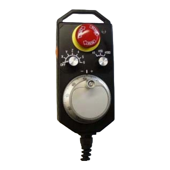
Page 16: Pulsar Input
Basic description of PCL series 10. Pulsar input 50oo 61oo 60oo (1) What is a pulsar? Generally, pulsars look like the one in Figure 17. The rotating dial is equipped with an encoder, and can be turned with the handle on the dial. The dial is just like the dial on a safe. -
Page 17: Stepper Motor Out-Of-Step Detection Function
Basic description of PCL series (2) Manual pulsar input on the PCL This is a function used to receive encoder signals from some other encoder than the feedback encoder on the back of the motor. Then, pulses can be output from the OUT and DIR terminals. A manual pulsar is not used to output pulses like a start command. - Page 18 Starting on the next page we would like to describe enhanced control functions such as interpolation controls and a target position override function, using the PCL6025/6045B for our example (the top of the line NPM pulse control models). The following descriptions are taken from instruction manual for the PCL6025/6045B. The PCL6025/6045B have all the functions that are described in this document.
-
Page 19: Instructions For The Pcl60Oo Series
Basic description of PCL series Instructions for the PCL60oo series Outline After receiving control commands from a CPU bus interface, the PCL6025/6045B controls stepper motors and servomotors that are driven by pulse train inputs. One of these LSI chips provides independent control (variable continuous operation, zero return operation, and positioning operation using constant speed, linear acceleration/deceleration, S-curve acceleration/deceleration) of two or 4 axes, linear interpolation between two to four axes and arc interpolation between two axes. -
Page 20: What Is Synthesized Constant Speed Control
Basic description of PCL series *** What is synthesized constant speed control? ***** Figure 3 shows the locus of a two-axis interpolation operation. Following the basic pulses sent to the main axis, pulses are output to each axis. In the figure, when both the X and Y axis pulses are output, they have to feed longer distance (x √... -
Page 21: Point 3. Various Acceleration/Deceleration Patterns
Basic description of PCL series POINT 3. Various acceleration/deceleration patterns Each speed pattern can specify the following Figure 6 [Speed pattern] elements independently: Acceleration rate Deceleration rate - Initial speed Operation speed - Operation speed - Acceleration speed characteristics Deceleration Acceleration S-curve range (acceleration rate, acceleration S-curve... -
Page 22: [Operation Speed Override]
Basic description of PCL series [Operation speed override] By changing the speed settings during operation, you can change the speed and the acceleration rate. (1) When the operation speed is changed to a lower speed than the preset while accelerating, and if the new speed <... - Page 23 Basic description of PCL series (○ : Can count, Blank: Can’t count) Counter1 Counter 2 Counter 3 Counter 4 Command Mechanical General-purpo Counter name Deflection position position Up/down Up/down Deflection Up/down Counter type counter counter counter counter Bit length ○ ○...
- Page 24 Basic description of PCL series POINT 7. Other useful functions ■ Manual operation input The manual operation input can be used to allow an operator to operate a motor with switches or a manual pulsar, instead of through a CPU. Using a manual pulsar or switch input, each axis can be operated independently.
- Page 25 Basic description of PCL series ■ Mechanical input signals The following four signals can be input for each axis: 1) +EL --- When this signal turns ON while operating in the positive direction, the motor stops immediately, or decelerates and stops. 2) -EL --- When this signal turns ON while operating in the negative direction, the motor stops immediately, or decelerates and stops.
- Page 26 Basic description of PCL series POINT 8. A variety of operation modes Roughly speaking, the PCL series have 18 operation modes. Command continuous Starts by a start command, stops by a stop command. operation Pulsar continuous After writing a start command, synchronizes pulsar input with output operation pulses.
- Page 27 Asia/Europe: Nippon Pulse Motor Co., Ltd. 2-16-13 Hongo, Bunkyo-ku, Tokyo 113-0033, Japan TEL: 81-3-3813-8841 FAX: 81-3-3813-7049 Web: http//www.pulsemotor.com E-mail: int-l@npm.co.jp North/South America: Nippon Pulse America, Inc. 1073 East Main Street, Radford, VA 24141, U.S.A. TEL: 1-540-633-1677 FAX: 1-540-633-7049 Web: http//www.nipponplse.com...
Need help?
Do you have a question about the PCL-240 Series and is the answer not in the manual?
Questions and answers