Table of Contents
Advertisement
Quick Links
Operating instructions
Machine designation:
Machine type:
Machine no.:
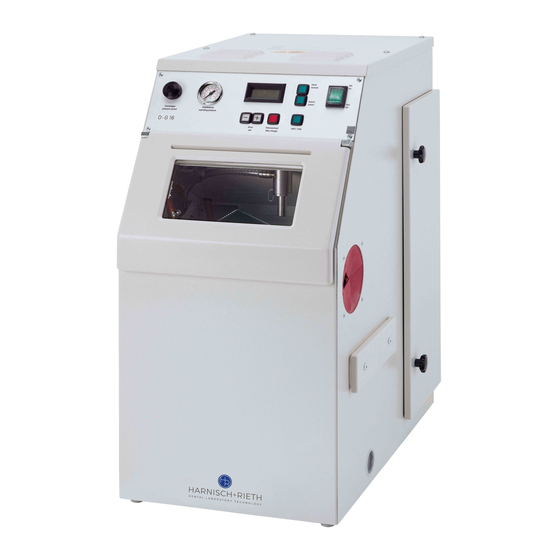
Automatic blasting unit
D-G 16 S2
...........................
Keep for future reference!
Maschinenbau
Werkzeuge
Laborgeräte
Hausanschrift:
Harnisch+Rieth
GmbH & Co. KG
Küferstr. 14 - 16
D-73650 Winterbach
Telefon
+49 7181 / 96 78-0
Telefax
+49 7181 / 7 31 39
+49 7181 / 96 78-17
E-mail:
info@hr-dental.de
http://www.hr-dental.de
Advertisement
Table of Contents

Related Manuals for Harnisch+Rieth D-G 16 S2

Summary of Contents for Harnisch+Rieth D-G 16 S2
- Page 1 Maschinenbau Werkzeuge Laborgeräte Operating instructions Machine designation: Automatic blasting unit Machine type: D-G 16 S2 Hausanschrift: Machine no.: ......Harnisch+Rieth GmbH & Co. KG Küferstr. 14 - 16 D-73650 Winterbach Keep for future reference! Telefon +49 7181 / 96 78-0...
-
Page 2: Table Of Contents
4.5 Checking of the injector if blasting performance is reduced......12 4.6 Checking of other components..............14 Sandblasting area illumination ................. 14 Electrical fuse protection .................. 14 Access to electrical/pneumatic control system..........14 Warranty conditions................... 15 EC declaration of conformity ................16 D-G 16 S2 - 18.04.13 / Vers.: 1... -
Page 3: Safety
Use on people is prohibited! 1.2 Possible dangers The sandblasting unit D-G 16 S2 is safe if used properly, but with improper and negligent use there is a risk of injury from the sandblast emanating from the injector (eye or skin injuries). -
Page 4: Marking Of Safety References Contained In These Instructions
Pedal switch with cable and plug ................No. 67010 2 m PVC fabric hose, blue, Ø 8.2 x 6 with plug-in socket for rapid action coupling and coupling ring ......No. 72350 See delivery docket for any possible further accessories D-G 16 S2 - 18.04.13 / Vers.: 1... -
Page 5: Short Description Of Unit And Identification Of Components
6 Door for filter area 2 Shield 7 Hand through-grip(only on the right side) 3 4 x hexagon socket screws 8 Slide-in sieve 4 Front lid 9 Sand drain lid 5 Star handle D-G 16 S2 - 18.04.13 / Vers.: 1... - Page 6 3 4 x M5 hexagonal socket screws 15 Screws for injector mounting 4 Front lid 16 Knurled nut for slide-in sieve 10 Air outlet 17 Socket for foot switches 13 Mains socket (230 V /50 Hz) D-G 16 S2 - 18.04.13 / Vers.: 1...
- Page 7 30 Fine particle filter bracket 63 Rounded head screw 31 Sand aspirator basket 64 Sandblasting cage 33 Middle floor area 70 Injector for manual blasting 34 4 x screws for floor area 75 Orientation pin D-G 16 S2 - 18.04.13 / Vers.: 1...
-
Page 8: Process For Putting Into Operation
Polishing blasting agent Cat. 150 A (150 µm) Caution The unit is designed for use with Harnisch+Rieth blasting agents. Harnisch+Rieth are not liable for any malfunction or damage resulting from the use of other blasting agents. 1. Open front flap (2) -
Page 9: Fill Abrasives
3.3 Fill abrasives (see fig. 1 and 3, page 4 & 6) Caution The D-G 16 S2 automatic blasting unit should only be used with a correctly installed and un- damaged super-fine filter (7) and filter bag (14). 1. Open door to filter chamber (4) by unscrewing the two star grips (11). -
Page 10: Description Of How To Set And Save The Blasting Time
2. Do not adjust operating pressure at the pressure regulator (51) to more than 5 bar! The operat- ing pressure can be checked at the pressure gauge (52). 3. The sand blast (from the injector (70) for manual blasting) is released by activating the foot switch. D-G 16 S2 - 18.04.13 / Vers.: 1... -
Page 11: Automatic Cut-Out And Filter Change Warning Light
M (DIN 60335) are employed. 1. Open door to filter chamber (4) by unscrewing the two star grips (11). 2. Press the plastic connection (41) away from the connection piece (40) with both hands. D-G 16 S2 - 18.04.13 / Vers.: 1... -
Page 12: Cleaning The Shove-In Sieve (Embedded Material Residue)
1. Position unit with sand drainage outlet on table edge. 2. Drain blasting agent by removing plastic sand outlet cover (13). Note On this occasion, the shove-in sieve (8) should also be removed and cleaned. (See section “4.3”) D-G 16 S2 - 18.04.13 / Vers.: 1... -
Page 13: Checking Of The Injector If Blasting Performance Is Reduced
28 Air hose for injector (70) 22 Jet nozzle 29 Sandblasting area shield 23 Injector pin 70 Injector for manual blasting 24 Injector ring 71 Coupling nut 26 Abrasive aspiration hose 72 Hose fitting D-G 16 S2 - 18.04.13 / Vers.: 1... - Page 14 20 mm O rientation pin Ø 3x163 mm long T he cage side walls S andblasting must be parallel to the cage housing R ubber plate Fig. 7: Orientation of the jet nozzle D-G 16 S2 - 18.04.13 / Vers.: 1...
-
Page 15: Checking Of Other Components
Danger Switch off the main switch (12) and pull out the mains supply plug before accessing the electri- cal/pneumatic control system. The electrical/pneumatic control system is located under the unit cover (66). The unit cover is removed by unscrewing the 4x hexagonal socket screws (60). D-G 16 S2 - 18.04.13 / Vers.: 1... -
Page 16: Warranty Conditions
Fax no.: 0 71 81/ 73 13 9 ------------------------- ------------------------- -------------------------- ------------------------- -------------- für Fensterumschlag hier falten-------------- Machine Automatic blasting unit designation: D-G 16 S2 Maschine type: Duplicate Guarantee return form Maschine no.: Date of purchase: Dealer/Store: Harnisch+Rieth GmbH & Co. Maschinenbau... -
Page 17: Ec Declaration Of Conformity
Address of the manufacturer : Küferstraße 14-16, 73650 Winterbach Machine designation : Automatic blasting unit Machine type : D-G 16 S2 The following pertinent EC directives were applied: EC Machine Directive 2006/42/EG (29.12.2009) EC Machine Directive 2006/95/EG (29.12.2007) EMV Directive 2004/108/EC (20.07.2007)
Need help?
Do you have a question about the D-G 16 S2 and is the answer not in the manual?
Questions and answers